Einleitung

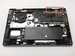
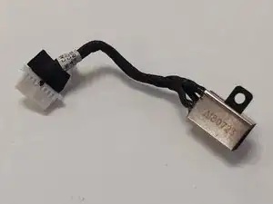
It may be a collective thought to think that replacing this port may prove difficult, however, it is a lot simpler than it may seem.

The power port is critical for this device's functionality, as there is no alternative method for providing power to this device such as a docking station or quick battery swapping.

  1. CYvRIHRfOgmYPPff
    CYvRIHRfOgmYPPff
    snVusWoOdRGZCRhS
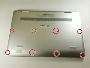
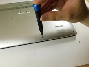
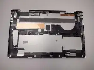
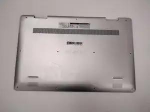
    • Remove the eight M2 5mm screws that secure the base cover using a Phillips #0 screwdriver.

  2. GW4dLMgyMemEOEKJ
    GW4dLMgyMemEOEKJ
    gJMDpufpML5gLDH2
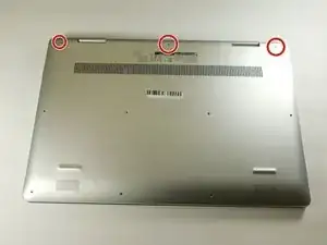
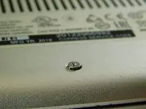
    • Loosen the three captive screws that secure the base closer to the hinges.

    • Do not attempt to remove the three captive screws! You need only to loosen them. They're supposed to stay on the base cover.

  3. lsVjQJaSEqsapufD
    lsVjQJaSEqsapufD
    3iD6RlPXbADHecg5
    DMEXkWSL6bYg3RiM
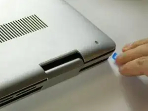
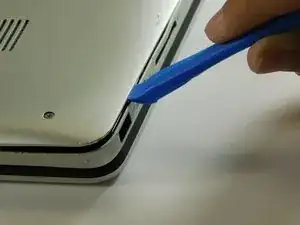
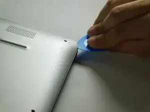
    • Carefully pry the base cover using an iFixit opening tool in the crevice near the hinges. Guide the pick along the edges and slightly lift upwards as you go along.

    • Do not start from the speaker end of the edges when opening, or you may cause further damage to your device!

  4. OyVXJtaoJNak1lpD
    OyVXJtaoJNak1lpD
    6bPBI3aoQCnefe3T
    P1BraqvDT2GINDAV
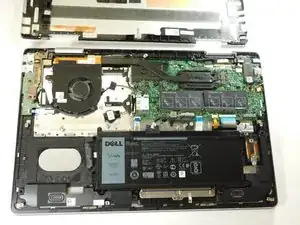
    • Carefully remove the base cover from the laptop.

  5. EXlnlK2aFWpmJB5r
    EXlnlK2aFWpmJB5r
    jsUShfQaxMlnSSkU
    nANkMStBjRpbvQsd
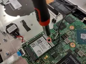
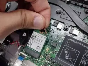
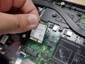
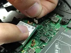
    • Remove the screw holding down the small bracket for the wireless card using a Phillips #0 screwdriver.

    • Remove the black wired connection from the port over the black triangle.

    • Remove the wire with the white marking from the port above the white triangle.

    • Pull the Wi-Fi card out of its slot.

  6. rINFqB5xY5teZCuK
    rINFqB5xY5teZCuK
    CSVRLiUSGk2opLKX
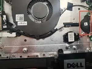
    • Gently remove the I/O cable.

  7. gEXhLR5BkPhLGIBc
    gEXhLR5BkPhLGIBc
    SAmZHUEDaT4AebPd
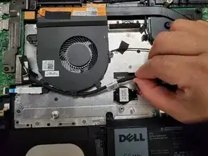
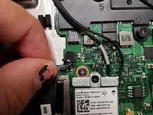
    • Remove the fan cable from the motherboard.

  8. V1QUrNvQRDYgJaGA
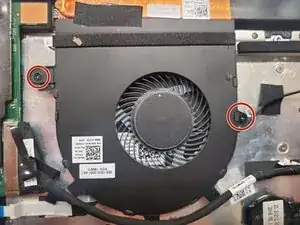
    • Remove two 3 mm screws that secure the fan using a Phillips #0 screwdriver.

  9. 5A6yDDHp16LKOGAC
    5A6yDDHp16LKOGAC
    qyQJCXyRiGTTLGNF
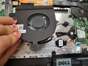
    • There is a little piece of tape/sticker on the fan that connects it to the heat sink. Gently remove this.

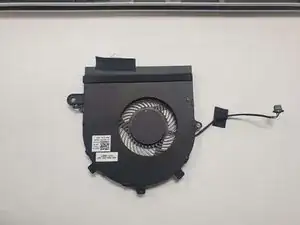
    • Lift the fan off the palm rest assembly.

  10. WPIkyONESbF5AWYI
    WPIkyONESbF5AWYI
    GbAj42TWBbF1tBnd
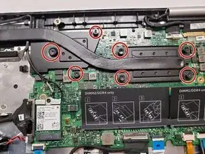
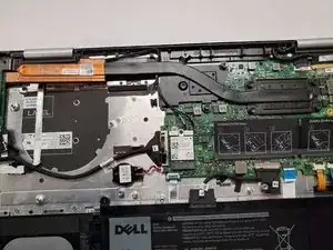
    • Loosen seven 3 mm captive screws securing the heatsink to the motherboard using a Phillips #0 screwdriver.

  11. o5JeKqKUGCeuUraS
    o5JeKqKUGCeuUraS
    NUGclxRIxnR3is6Y
    sqVmJBYGXYdL45Jp
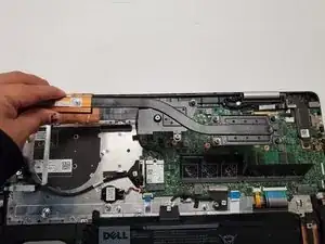
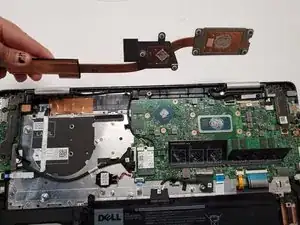
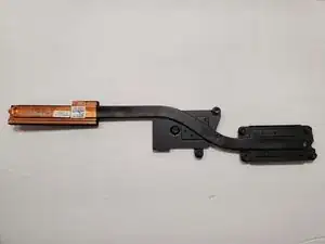
    • Lift the heatsink off the motherboard.

  12. VqZAFvTPt4CG6BYE
    VqZAFvTPt4CG6BYE
    onnCwcVRx2hAyZ3D
    • Ensure that you have your device opened flat at a 180 degree angle. This will make removal easier.

  13. PoEnPjAyILavEAMW
    PoEnPjAyILavEAMW
    wDUpUMgWknIWQSl1
    mxEIEqY2JGPyQuFq
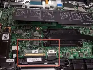
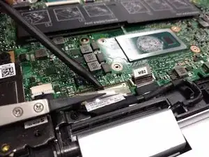
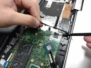
    • Locate the ribbon cables for the assembly on the right hand side marked "MB1" and "MB2."

    • The "MB1" ribbon is locked with a copper/brass colored handle that must be lifted upwards. Then you can remove the ribbon by pulling it away from the socket.

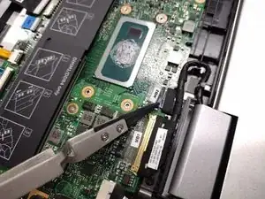
    • The "MB2" ribbon is locked in its socket with a black latch. Using a non-metallic precision tool (such as tweezers) lift the latch and pull away the MB2 cable.

  14. ZnENUACdfVpXaUkZ
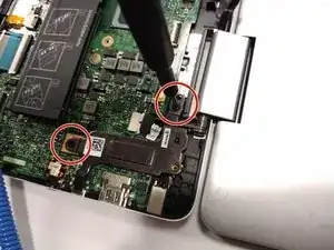
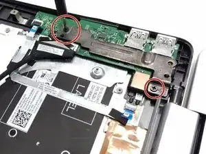
    • Remove the two screws holding down the assembly on the right hand area using a Phillips #00 screwdriver.

  15. NGgWAB3Xh25mS1Mj
    NGgWAB3Xh25mS1Mj
    tpo3unvyfLs21nLS
    EQqCxhgRSXQXGtIO
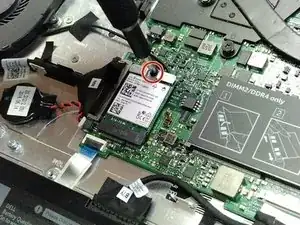
    • Remove the screw protecting the endpoints of the NIC cables and NIC chip using a Phillips #0 screwdriver.

    • Gently pull away the cabling from the NIC chip.

    • The wires can be removed without removing the heat sink, though this is not advised if you are not familiar with the layout.

  16. 1HJKyTYbKkvW16PO
    • Remove the two screws holding down the bracket of the assembly on the left hand side using a Phillips #0 screwdriver.

  17. fcYAnig5Y6DJ21y6
    fcYAnig5Y6DJ21y6
    qopTU2YjH1HmKfS2
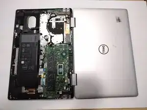
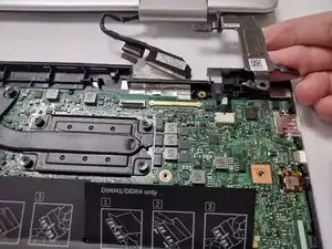
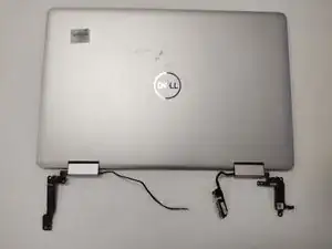
    • Lift the display assembly upwards away from the palm/main assembly.

  18. RKsAEhET6yXAtTIQ
    RKsAEhET6yXAtTIQ
    NekDfvDWPnwuicqH
    F3WYoNsTVbnR4Yc2
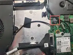
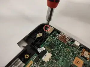
    • Remove the single 3 mm screw that secures the port using a Phillips #0 screwdriver.

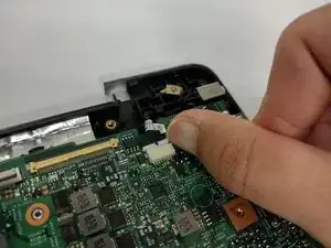
    • Disconnect the cable from the port by gently wiggling and pushing the plug away from the port.

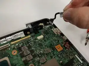
    • Pull the disconnected cable upwards, and the rest of the power port will follow.

Abschluss

To reassemble your device, follow these instructions in reverse order.
Antonio Franco

Mitglied seit: 25/08/22

1001 Reputation

0 Kommentare