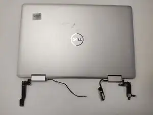
Einleitung

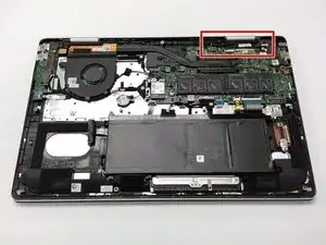
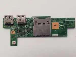
The I/O board features 2 USB ports and an SD card reader that sits on the left side of the laptop. This component is also responsible for the power on function, as the component that presses the power button is the fingerprint reader.

  1. CYvRIHRfOgmYPPff
    CYvRIHRfOgmYPPff
    snVusWoOdRGZCRhS
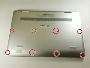
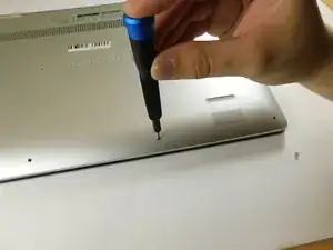
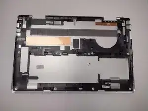
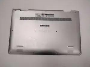
    • Remove the eight M2 5mm screws that secure the base cover using a Phillips #0 screwdriver.

  2. GW4dLMgyMemEOEKJ
    GW4dLMgyMemEOEKJ
    gJMDpufpML5gLDH2
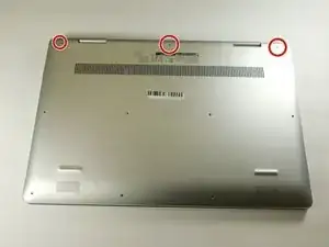
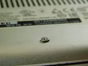
    • Loosen the three captive screws that secure the base closer to the hinges.

    • Do not attempt to remove the three captive screws! You need only to loosen them. They're supposed to stay on the base cover.

  3. lsVjQJaSEqsapufD
    lsVjQJaSEqsapufD
    3iD6RlPXbADHecg5
    DMEXkWSL6bYg3RiM
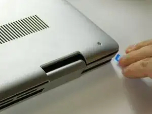
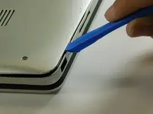
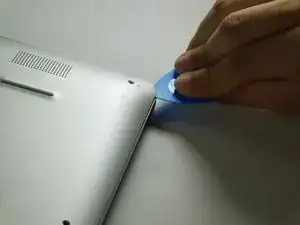
    • Carefully pry the base cover using an iFixit opening tool in the crevice near the hinges. Guide the pick along the edges and slightly lift upwards as you go along.

    • Do not start from the speaker end of the edges when opening, or you may cause further damage to your device!

  4. OyVXJtaoJNak1lpD
    OyVXJtaoJNak1lpD
    6bPBI3aoQCnefe3T
    P1BraqvDT2GINDAV
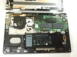
    • Carefully remove the base cover from the laptop.

  5. EXlnlK2aFWpmJB5r
    EXlnlK2aFWpmJB5r
    jsUShfQaxMlnSSkU
    nANkMStBjRpbvQsd
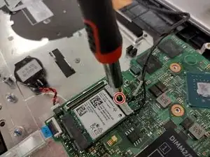
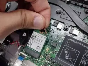
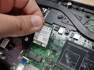
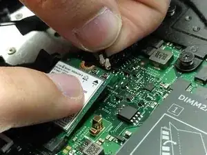
    • Remove the screw holding down the small bracket for the wireless card using a Phillips #0 screwdriver.

    • Remove the black wired connection from the port over the black triangle.

    • Remove the wire with the white marking from the port above the white triangle.

    • Pull the Wi-Fi card out of its slot.

  6. rINFqB5xY5teZCuK
    rINFqB5xY5teZCuK
    CSVRLiUSGk2opLKX
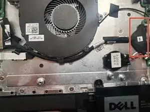
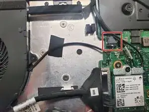
    • Gently remove the I/O cable.

  7. gEXhLR5BkPhLGIBc
    gEXhLR5BkPhLGIBc
    SAmZHUEDaT4AebPd
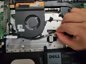
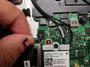
    • Remove the fan cable from the motherboard.

  8. V1QUrNvQRDYgJaGA
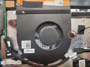
    • Remove two 3 mm screws that secure the fan using a Phillips #0 screwdriver.

  9. 5A6yDDHp16LKOGAC
    5A6yDDHp16LKOGAC
    qyQJCXyRiGTTLGNF
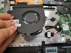
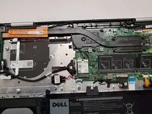
    • There is a little piece of tape/sticker on the fan that connects it to the heat sink. Gently remove this.

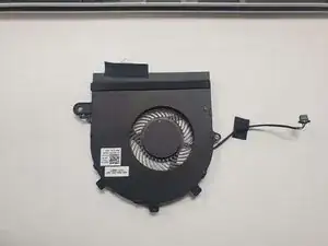
    • Lift the fan off the palm rest assembly.

  10. WPIkyONESbF5AWYI
    WPIkyONESbF5AWYI
    GbAj42TWBbF1tBnd
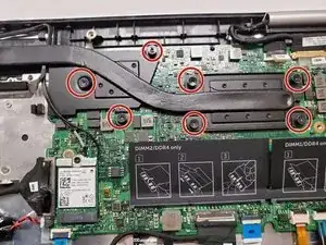
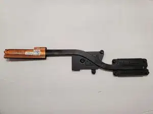
    • Loosen seven 3 mm captive screws securing the heatsink to the motherboard using a Phillips #0 screwdriver.

  11. o5JeKqKUGCeuUraS
    o5JeKqKUGCeuUraS
    NUGclxRIxnR3is6Y
    sqVmJBYGXYdL45Jp
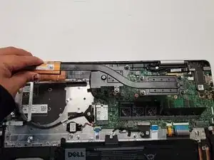
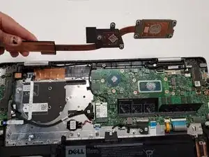
    • Lift the heatsink off the motherboard.

  12. VqZAFvTPt4CG6BYE
    VqZAFvTPt4CG6BYE
    onnCwcVRx2hAyZ3D
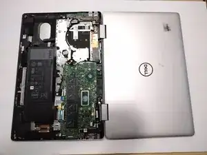
    • Ensure that you have your device opened flat at a 180 degree angle. This will make removal easier.

  13. PoEnPjAyILavEAMW
    PoEnPjAyILavEAMW
    wDUpUMgWknIWQSl1
    mxEIEqY2JGPyQuFq
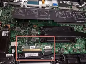
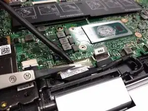
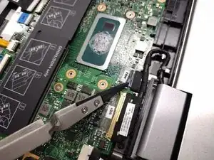
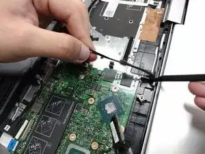
    • Locate the ribbon cables for the assembly on the right hand side marked "MB1" and "MB2."

    • The "MB1" ribbon is locked with a copper/brass colored handle that must be lifted upwards. Then you can remove the ribbon by pulling it away from the socket.

    • The "MB2" ribbon is locked in its socket with a black latch. Using a non-metallic precision tool (such as tweezers) lift the latch and pull away the MB2 cable.

  14. ZnENUACdfVpXaUkZ
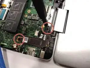
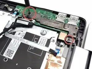
    • Remove the two screws holding down the assembly on the right hand area using a Phillips #00 screwdriver.

  15. NGgWAB3Xh25mS1Mj
    NGgWAB3Xh25mS1Mj
    tpo3unvyfLs21nLS
    EQqCxhgRSXQXGtIO
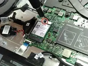
    • Remove the screw protecting the endpoints of the NIC cables and NIC chip using a Phillips #0 screwdriver.

    • Gently pull away the cabling from the NIC chip.

    • The wires can be removed without removing the heat sink, though this is not advised if you are not familiar with the layout.

  16. 1HJKyTYbKkvW16PO
    • Remove the two screws holding down the bracket of the assembly on the left hand side using a Phillips #0 screwdriver.

  17. fcYAnig5Y6DJ21y6
    fcYAnig5Y6DJ21y6
    qopTU2YjH1HmKfS2
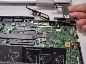
    • Lift the display assembly upwards away from the palm/main assembly.

  18. ijiBBMpK5qTMniPy
    ijiBBMpK5qTMniPy
    b3QfAMblC6gcyOKM
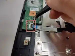
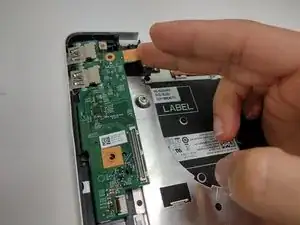
    • Lift the latch holding down the ribbon cable on the I/O board, then pull it away using the blue tab.

    • Lift the I/O board upwards to remove it from the assembly.

Abschluss

To reassemble your device, follow these instructions in reverse order.
Antonio Franco

Mitglied seit: 25/08/22

1001 Reputation

0 Kommentare