Einleitung

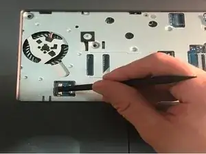
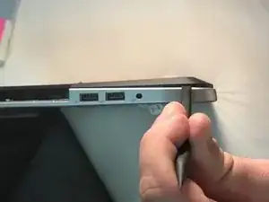
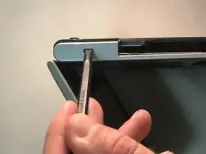
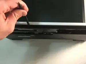
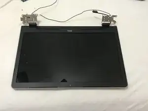
This guide will show you how to replace the LCD Screen on the Dell Inspiron 5758.

Prerequisite guides are:

  • Battery
  • Hard Drive
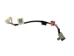
  • DC Jack
  • Keyboard
  1. XRiURGgjGuA6KdLg
    XRiURGgjGuA6KdLg
    vscaWgcqAP6XXCsP
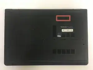
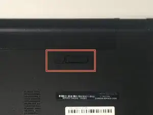
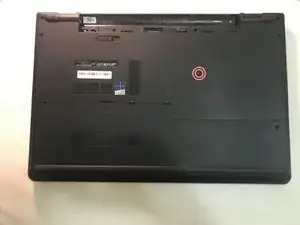
    • Flip the laptop with the serial number facing up. You should be able to see the battery release switch.

  2. Y2arA52PP6XaSHwX
    Y2arA52PP6XaSHwX
    BZglqLlLUOptWMG5
    EnaZVYVsGLNvGDj4
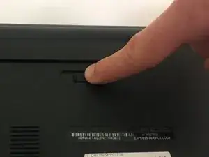
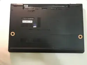
    • Slide the battery release switch towards the unlock icon.

    • You should hear a click.

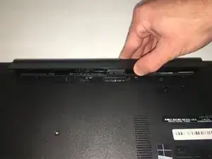
    • Lift and pull the ejected battery to remove it.

  3. RYFljTiJFniCEwxV
    RYFljTiJFniCEwxV
    sWWwPWDirnsHYXLZ
    1MQJYOXhRWnP5KvQ
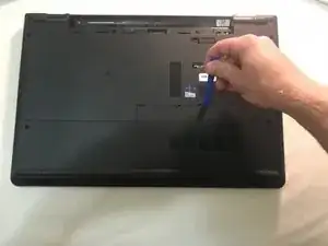
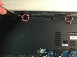
    • Remove the one 3mm optical drive screw.

    • Remove the two 8 mm screws.

    • Pry up and remove the access door.

  4. mIauiTmMeE6ETDy3
    • Remove the one 3 mm screw.

    • Remove the bracket.

  5. OfMacxLFsWMDNJNx
    OfMacxLFsWMDNJNx
    6tvIJkofRdHjydmi
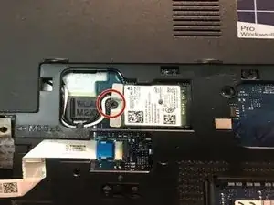
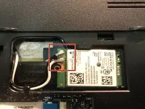
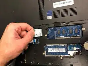
    • Unplug the antenna cables.

    • Remove the Wireless Card.

  6. ahr2oDKBCgOHZN3S
    ahr2oDKBCgOHZN3S
    iNThgHwDcGCc1ScE
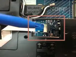
    • Unplug the hard drive cable.

    • Use a plastic opening tool or your fingernail to pop the tab of the cable connector. Then you will be able to disconnect the cable.

    • Remove the four 8 mm screws.

    • Remove the hard drive.

  7. qnx2cm4uNRE1OwCV
    qnx2cm4uNRE1OwCV
    JYjRKSr3Tw3yhZqd
    lFadSVVOEm1ZhU6X
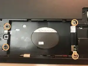
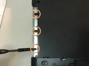
    • Remove the two 3 mm screws under the battery.

    • Remove the three 2 mm wafer screws under the optical drive.

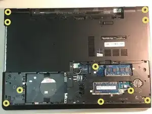
    • Remove the ten 8 mm base screws.

  8. PBCmDTa1kp3oALhf
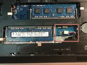
    • Unplug the speaker cable by sliding to the right.

  9. vIkYUeYCZCkhAjjr
    vIkYUeYCZCkhAjjr
    SHPjrVD5Vpp4XvhK
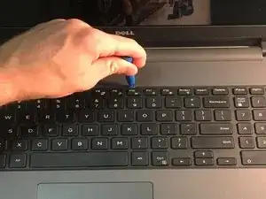
    • Press in the tabs to loosen the keyboard.

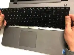
    • Carefully lift the keyboard up and turn it over.

  10. VvsNJ5nsHbISh4ZI
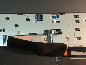
    • Unplug the keyboard cable & remove the keyboard.

  11. WXkY3ecGFcuFVdlk
    WXkY3ecGFcuFVdlk
    yYSOfYTvrZHovMWL
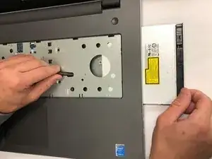
    • Slide the DVD optical drive over & remove it from the laptop.

  12. alZvT2IMqnSsgcMs
    alZvT2IMqnSsgcMs
    dXkTO4xwFxNBdKZ4
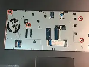
    • Remove the four 5 mm screws.

    • Unplug the optical drive interposer cable.

  13. UrZLIajHrkUxboBF
    UrZLIajHrkUxboBF
    dbNa1o3FYSYWZ6F4
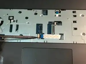
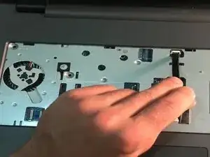
    • Unplug the power button cable.

    • Unplug the touchpad cable.

  14. dndjSFcGArnJQEcs
    dndjSFcGArnJQEcs
    Y5HHY5sbwRYgfkXh
    PjYBq3wZ1ZvEahks
    • Carefully pry off & loosen the bottom base.

  15. V3SfmMUrRd1DgJFU
    • Remove the bottom base.

  16. eqGWn3byWOrEpMuV
    eqGWn3byWOrEpMuV
    PjPSdKXj5sZIiKKC
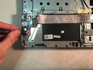
    • Remove the one 5mm screw.

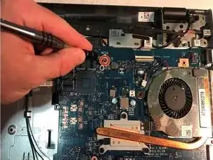
    • Lift the circuit board & turn it over.

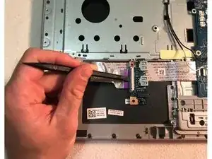
    • Unplug the cable.

    • Remove the audio/USB circuit board.

  17. QTBrBSNCBFqgmolL
    QTBrBSNCBFqgmolL
    sDna4dONnJk61QmI
    lFdgVTWDICHMqJZB
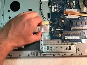
    • Loosen the audio / USB cable.

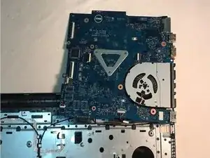
    • Remove the one 3mm motherboard screw.

    • Lift the motherboard & carefully move it out of the way.

  18. vJUgtjx4mNFZnTOL
    vJUgtjx4mNFZnTOL
    wXCZCfD1UFTBwdW4
    OaRxVnbhXtVV332U
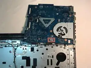
    • Unplug the DC jack cable.

    • Remove the one 3mm screw.

    • Remove the DC Jack.

  19. KgdZuHIqLflQlVQV
    KgdZuHIqLflQlVQV
    aBtiWJVG6uIJEmd6
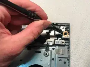
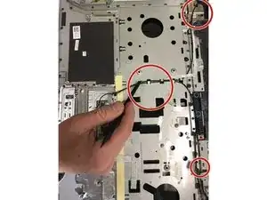
    • Release the antenna cable tape.

    • Release the antenna cables.

  20. o6yInuZKl4lVvsQq
    o6yInuZKl4lVvsQq
    PTkfYypOGerllaDD
    p2SBXjaGIociN1QG
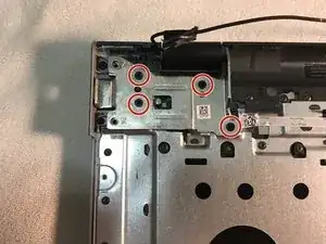
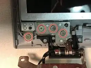
    • Remove the four 5mm right hinge screws using the Phillips #00 screwdriver.

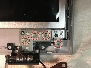
    • Remove the three 5mm left hinge screws using Phillips #00 screwdriver.

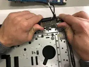
    • Open the hinges carefully and remove the LCD display assembly.

  21. JsjtQbBI2wqL2TIT
    JsjtQbBI2wqL2TIT
    GGvwBEmwIs4YtIbY
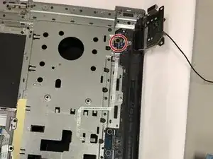
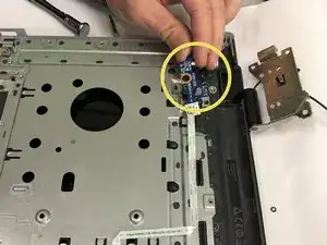
    • Remove the one 2mm wafer screw using Phillips #0 screwdriver.

    • Loosen the cable and remove the power button circuit board.

  22. pPftPDwZdnrCRrBn
    pPftPDwZdnrCRrBn
    yMJfcBApYhIjG5GJ
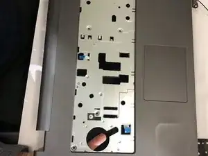
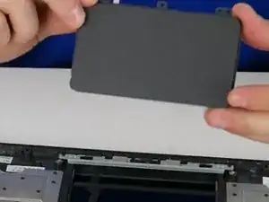
    • Push up on the touchpad to release it from the housing.

    • Remove the touchpad.

  23. HirFW1nrXeYaRIt3
    HirFW1nrXeYaRIt3
    NhHbo3eBgWOGyYEJ
    vsBErVtHUBHZeMcP
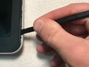
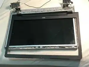
    • Once you have removed the LCD display assembly from the palmrest touchpad, use a spudger to unsnap the LCD bezel via the notches on the outside edge of the bezel .

    • The bezel may require some force to unsnap.

    • When you have removed the LCD bezel, place it to the side.

  24. LyoAbfvH1Mi6nacw
    LyoAbfvH1Mi6nacw
    WKjKUBFDyAxcVDPl
    j12JaBaUBx4BifkR
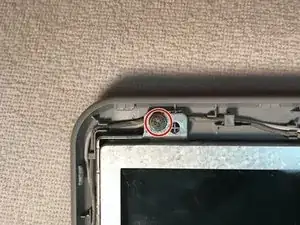
    • Remove the ten 4.5mm screen screws.

    • There is one screw in the top left, one screw in the top right, four in the bottom left, and four in the bottom right.

  25. 6PCjEInO1lVpBapy
    6PCjEInO1lVpBapy
    Jplksd1WCDIppoKt
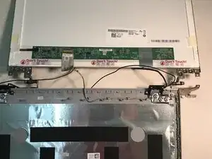
    • Lift the LCD screen from the display assembly, flip the LCD screen over, and place the screen face down.

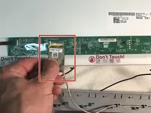
    • Unplug the LCD cable.

    • Place the display assembly to the side.

  26. FyRoclIOCHdkl2UI
    FyRoclIOCHdkl2UI
    oalkQGd2dncu5v4s
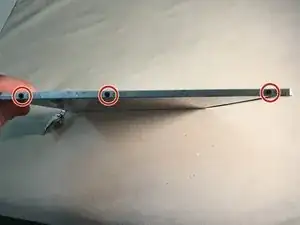
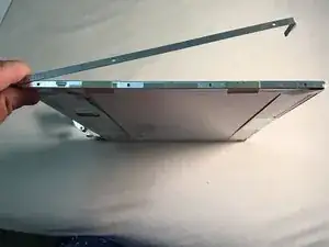
    • Remove the three 3mm screws that connect each hinge rail to the LCD screen.

    • Remove the hinge rails.

    • There are two hinge rails, one on the left edge of the screen and one on the right edge.

Abschluss

To reassemble your device, follow these instructions in reverse order.
Blase Martin

Mitglied seit: 18/09/18

398 Reputation

0 Kommentare