Einleitung

  1. TOdTjpkb45FovFEF
    • Make sure that the computer is turned off and is disconnected from external power source.

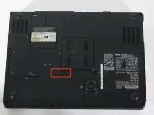
    • Turn it upside down and locate the battery release switch.

    Introduction: Parts: Need to add the Fan Part Numbers

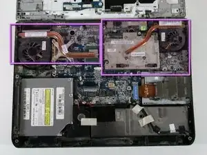
    Original equipment: CPU Fan DC28A000820, GPU Fan DC28A000920

    John Frazier -

  2. JGpfhAlcMRt6PDQf
    JGpfhAlcMRt6PDQf
    YsDcehP3sPdKYgYH
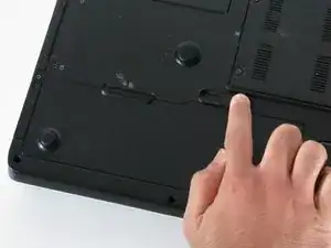
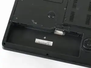
    • While holding the switch in the open position, lift out the battery.

    • If you plan to work on any internal laptop components, press and hold the power button for 5 seconds. This will dissipate any residual charge on the motherboard to prevent electrical shock when you begin to handle it.

  3. fDBHHPQEcNyEvmXB
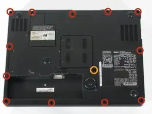
    • Remove the 12 Phillips #1 screws from the edges of the lower case.

    • You may also need to remove the central screw next to the lock icon.

    Need to add a step to open the Wi-Fi cover, uper left with the Microsoft label on it. Then detach the Wi-Fi antenna wires from the pc board.

    John Frazier -

  4. SMmwKYXCCEbn2u3B
    SMmwKYXCCEbn2u3B
    FhpIrM5qVJT2LdFv
    TWRoE2plx6XHWYXC
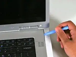
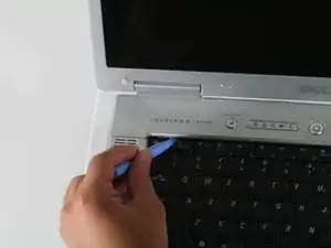
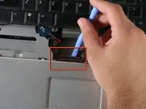
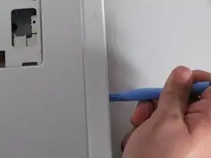
    • Turn the computer back over and tilt the screen open.

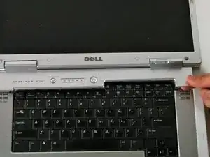
    • Use the plastic opening tool to carefully pry the panel out as shown in the pictures

    • Remove the plastic panel carefully.

  5. kyLWuF1iHaY16dCg
    kyLWuF1iHaY16dCg
    XAmU6xmdiQtfaCN6
    pEt1XB1CjDoCPLNN
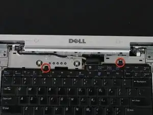
    • Use the small Phillips head screwdriver to remove the screws circled in red.

    • Gently lift the keyboard up and rest it just below the screen as shown in the picture.

    • The keyboard will still be connected to the motherboard.

  6. TfLJq4FKltJynHsn
    TfLJq4FKltJynHsn
    cXtpsRPrkbKwJH1o
    • Before removing the keyboard completely, use the plastic opening tool to gently lift the clamp connecting the keyboard to the motherboard.

    • Once the keyboard has been disconnected, remove the keyboard completely.

  7. b2Z3yLYHWRAAN34U
    b2Z3yLYHWRAAN34U
    4BOTRsW2KTsDo4rG
    ghMJ2stLInZOcttE
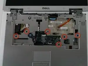
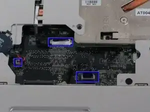
    • Using a Phillips head screwdriver, remove the screws shown in the image. They all have the letter "P" next to them.

    • Carefully unplug the connections shown.

    • Don't forget the display cable. It is slightly to the right of the Dell logo at the top.

    • Also, the wireless cables on the right side may prevent moving the upper case out of the way.

    • Once the screws have been removed and the connections unplugged, use the plastic opening tool to gently separate the panel from the lower case.

    It probably better to leave the small blue battery to the left plugged in for the Bios Chip. Just lift the batter out of its holder and move it out of the way as the cover is moved. If unplugged the computed will ask you to run setup when you start the computer.

    John Frazier -

  8. E6RoSrylCslBTJDZ
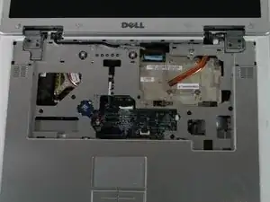
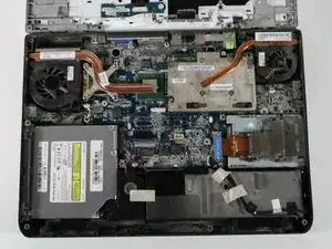
    • Remove the plastic case by gently bending back towards the screen. You can bend the screen all the way back if that helps.

    • For the motherboard the optical drive will be removed already. However for the lower case it is not necessary that it be taken out.

    • If you are having trouble removing the upper plastic case (and LCD) from the lower case, there may still be a wire connected to the Wi-Fi adapter. Turn the laptop over, open the Wi-Fi module access panel and remove the + and - leads for the Wi-Fi antenna.

    Need to add a caution when rotating the cover to be careful with the hinge post on the right side. you can snag the GPU heat pipe as you rotate the cover. So watch the maneuver.

    John Frazier -

  9. GqPxahAMdRWY5Mp6
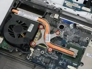
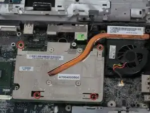
    • Unscrew the 4 screws shown in the picture.

    • Screws will not come out all the way.

  10. uDKE3UMG4lkODNN1
    uDKE3UMG4lkODNN1
    Uw3mGCq2v6bshHVw
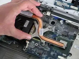
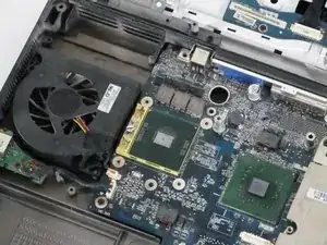
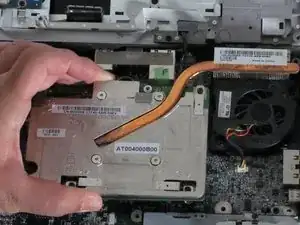
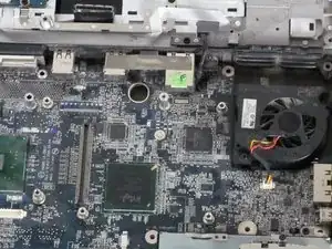
    • Remove the heat sync gently

  11. AHCyqZU4QwlAGaBV
    AHCyqZU4QwlAGaBV
    g5BAEcoVo22Qm5cJ
    1yHlkAdUJKw1fYLg
    • The right heat sync is connected to the videocard. To remove the heat sync requires also removing the videocard.

    • Remove the 4 screws indicated in the first picture

    • Screws will not totally come out.

    • Gently lift up the videocard and heat sync from the motherboard.

    Note: There are two different types of motherboards for the E1705/9300/9400. One with discreet graphics (DF047) and one with integrated graphics (FF055). You can tell which if the system has 1 or 2 cooling fans. Systems with discreet graphics will have a second cooling fan in upper right as shown in the picture. Integrated graphics will not have the same video card as shown nor a second cooling fan. The motherboards are pinned out to support the fans as well as the base which has a open air flow vent.

    techforkids -

Abschluss

To reassemble your device, follow these instructions in reverse order.
Malik Shahbal

Mitglied seit: 06/10/10

471 Reputation

0 Kommentare