Einleitung

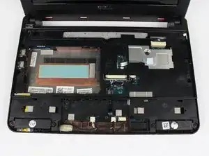
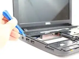
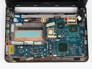
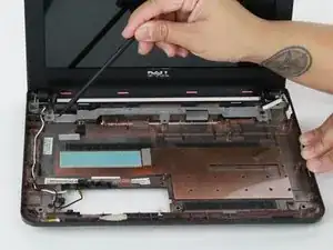
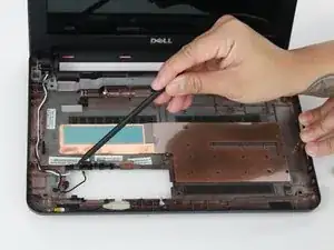
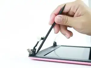
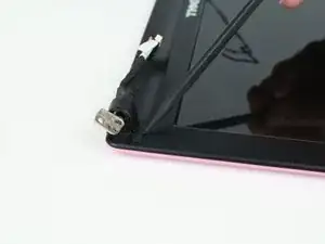
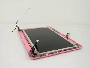
This guide will take you through removing the display. This may be a necessary process if the display is not functioning properly or is broken. The display panel and motherboard are extremely fragile so remember when replacing to handle with care and consider placing onto a towel.

  1. fNf43O1bwcsAXEeW
    • To prevent injury and loss of data, ensure the device is turned off.

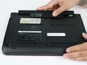
    • Slide the release latches out toward the edges to unlock the battery.

  2. BU2lkoVWHAx6JmSx
    • Remove the battery by pulling it up and out.

  3. r15X1bBTKXyGISlf
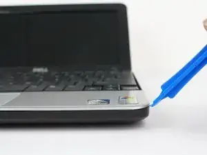
    • Using a prying tool, gently pry the palm rest off of the palm rest bracket. Start prying from one side and slowly work your way around.

    • Carefully remove the palm rest from the computer base since it is still connected by a cable and to avoid damage to the palm rest.

    Skip this step! there is no need to do it!

    Mikhail Telnov -

  4. 6EjdxadC2hEL5Yjl
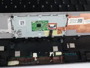
    • Gently pull the touchpad cable off the palm rest bracket.

    • Lift the rest of the palm rest off the computer base.

    Skip this step! there is no need to do it!

    Mikhail Telnov -

  5. yToR1Di1nrCd5mBB
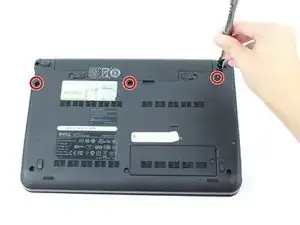
    • Remove the three 8mm Philips 0 screws securing the keyboard.

  6. xkbM6QtofTXMJLCM
    • Turn over the device and open the display.

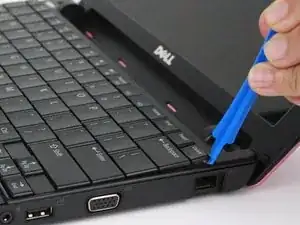
    • Gently pry open the keyboard with the plastic opening tool, working under the edges to release the clips.

  7. tjG1ZEDAMus4dGIC
    tjG1ZEDAMus4dGIC
    sgqSHfu2RVTP2SCG
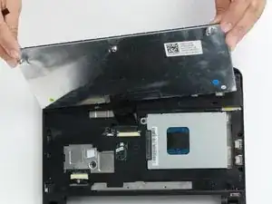
    • Lift the keyboard off of the support bracket carefully since it is still connected by a ribbon cable.

  8. FYZpBcj1ueT5upLx
    FYZpBcj1ueT5upLx
    OT6uHCkNaQUhdugr
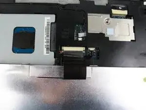
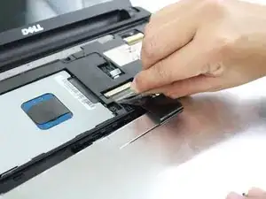
    • Push the clips out on either side of the ribbon cable to release it.

    • Gently disconnect the ribbon cable by pulling on the clear tab.

    • Remove the keyboard.

  9. DBynQclGdYCWnJn2
    • Close the device and turn over.

    • Remove the five 8mm Phillips 0 screws.

  10. kKct4jECSkUBfSkx
    kKct4jECSkUBfSkx
    rDXgjvp4j6yOdejw
    • Turn the device over and open the display.

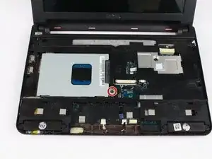
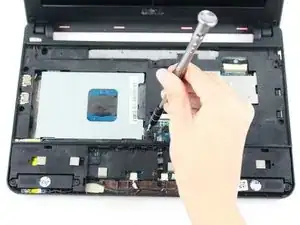
    • Remove the single 8mm Phillips 0 screw attaching the hard-drive cage to the body of the device.

  11. CemRFdTVGNdptKjH
    CemRFdTVGNdptKjH
    PFJOyKjqKBaR1DX5
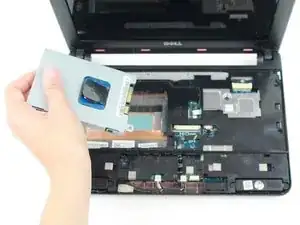
    • Pull on the black tab and slide the hard-drive cage toward the USB port on the left side of the device until its comes free and carefully lift out of device.

  12. oMXvTvNaUi3vhGXB
    oMXvTvNaUi3vhGXB
    LcYgfLw2TYvnROcX
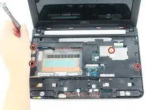
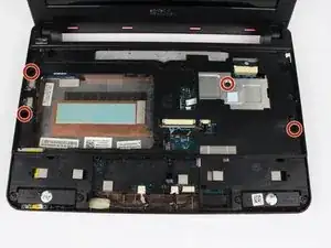
    • Remove the four 6mm Philips 0 screws securing the bracket.

  13. NiKybcMmBOv3lIVV
    NiKybcMmBOv3lIVV
    eWNJUqTbYJ2bQOVH
    KJKLbGamhvYYGNdE
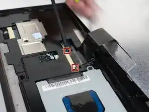
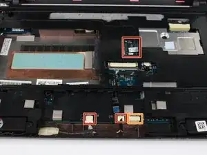
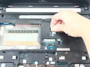
    • Disconnect the following:

    • Power button cable

    • Speaker cable

    • Power status light cable

    • Bluetooth cable (if installed)

  14. UjWrryKJPnxX5oAP
    • Gently pry off the bracket using the prying tool.

  15. XAMGNqSFi4H2faOu
    • Remove the following:

    • Two 4mm Phillips screws securing the motherboard

    • AC adapter cable

    • USB and SIM card cable connector

    • Display cable connector

    • Carefully lift the motherboard out.

  16. 6cSKCoicaaQL5gCD
    6cSKCoicaaQL5gCD
    GIjTiPZUAHRZgOkj
    • Pull the Mini-Card cables out of the computer base. They slide out from under a few pieces of plastic that secure them to the base.

  17. XhHNcHsWDglJRkWw
    XhHNcHsWDglJRkWw
    1hmY4jA2VxmJOJEN
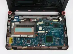
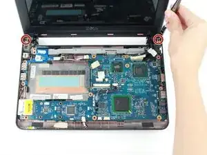
    • Remove the two 4 mm Phillips 0 screws that secure the display assembly to the computer base.

  18. cr36TB2Zhyo3bPVT
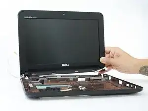
    • Lift and remove the display assembly from the computer base.

  19. KRJFoSGqCQaConV5
    • Press and remove the hinge cover caps using the spudger.

  20. GJLMgCjWExFSPANh
    • Remove the two rubber pads on the display bezel screws using a finger nail, prying tool or Spudger.

    • There is one on either side.

  21. 1HbRKuYSZiagmkQf
    1HbRKuYSZiagmkQf
    JiLPO5NTCQV6UFYu
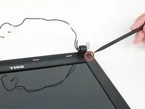
    • Remove the two 4 mm Phillips 0 screws on the display bezel.

  22. tCXNUTWRyAnJlQ44
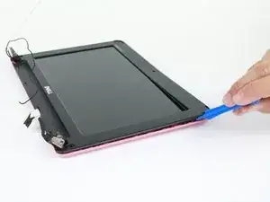
    • Using the plastic opening tool gently pry up the inside edge of the display bezel.

  23. i54TKA42gHkpJjWg
    • Remove the display bezel using a plastic prying tool.

  24. cBQHTpM1AWa1aGGb
    cBQHTpM1AWa1aGGb
    jXwiStriRaxNfVZU
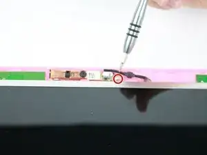
    • Remove the single 3mm Phillips screw securing the camera to the display panel.

  25. yByRxyfaTqejQm4r
    yByRxyfaTqejQm4r
    iUCSBZbC5ebOJHq5
    ATCMoJGJvdFHqjvB
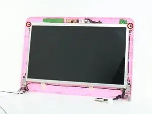
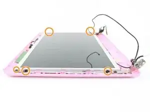
    • Remove the two 4mm Phillips 0 screws that are visible from the top.

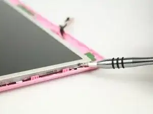
    • Remove the four 3mm Phillips screws on the side of the display panel securing it to the display cover.

  26. sYKl4ZuLYMviYnb6
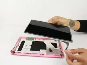
    • Remove the display panel.

    • The display panel is fragile, handle with care.

  27. 4tLLAYVvCQ2dE2CB
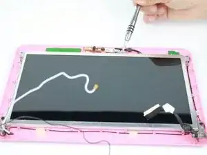
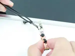
    • Disconnect the camera cable using tweezers.

  28. amUrjBsTrUFwuvUv
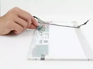
    • Remove the panel connector by pulling on the blue tab on the back of the display panel.

Abschluss

To reassemble your device, follow these instructions in reverse order.
Melissa Russell

Mitglied seit: 26/10/16

182 Reputation

0 Kommentare