Einleitung
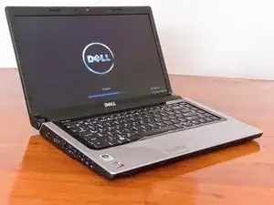
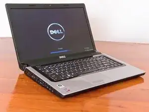
This is a disassembly guide for the Dell Studio 15 series that spans several models including the 153x, 155x and 156x. The laptop used for this guide is the 1557. If you have a Dell Studio 15 laptop chances are this guide will be applicable.
Werkzeuge
-
-
The Dell Studio 1557 is a part of the Studio 15 family of laptops. All share very similar components and design with each other.
-
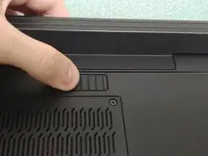
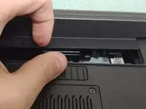
To start, turn the laptop over and remove the battery by pushing the sliding lock to the right and pulling the battery away from you.
-
-
-
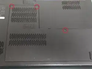
Loosen the three 5mm screws from the back panel using a #1 Philips screwdriver.
-
These screws should stay mounted on the back panel, when loosened pull up on the top part of the panel to remove it.
-
-
-
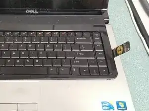
Turn the computer back over and open it up. You can pull up on the top end of the plastic bezel or insert an iSesamo (or similar pry tool) between the silver palmrest and black plastic lining the keyboard. Either way the plastic bezel should come up with ease.
-
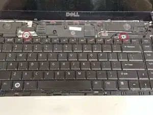
Remove the two 3mm screws securing the keyboard.
-
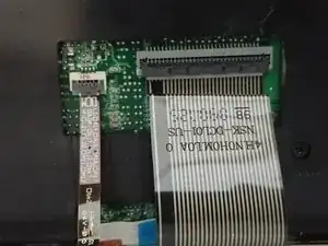
Gently pull up on the top end of the keyboard but do not remove it just yet. Under the keyboard pull up on the black tab that secures the cable (two cables if you have a backlit keyboard) and pull the cables toward you to remove.
-
-
-
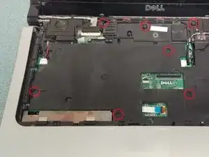
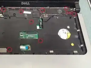
Remove the six 5mm screws and five 3mm screws. Take note of the placement to avoid mixing the screws and causing damage to the shell when putting them back.
-
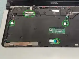
Disconnect the five cables that control the speakers, touchpad, webcam and screen. The touchpad has a tab that can be pulled up while the rest can be pulled out or up.
-
-
-
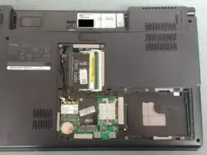
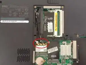
Turn the computer over but do not close the lid. Disconnect the three cables plugged into the WiFi card and route the cables out of the plastic. When you turn it back over to face the screen you should be able to pull the cables out.
-
Use a pry tool to separate the silver palmrest from the lower black chassis. Move around the perimeter of the palmrest until it becomes loose enough to pull off.
-
-
-
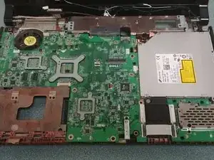
You should now be able to access the optical drive, card reader and motherboard.
-
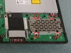
Remove the four phillips screws holding the card reader in place.
-
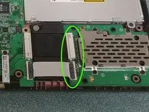
Disconnect both cables. The upper cable pulls out to the side while the lower has a tab that lifts up.
-
Lift up on the right side of the card reader board to remove it.
-
-
-
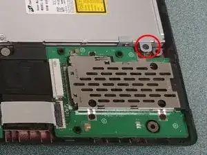
Remove the one phillips screw and slightly lift up on the right side of the optical drive then pull to the right to remove it from the motherboard.
-
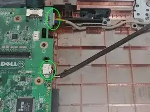
With the optical drive removed, pull the two cables under it to the right to remove them from the motherboard. These cables are for the charging port and right USB port.
-
-
-
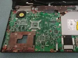
Remove the six phillips screws securing the motherboard.
-
Before removing the motherboard disconnect the cable for the subwoofer on the lower left corner.
-
Gently pull up on the right side of the motherboard and then to the right to free the left side ports and fully remove it.
-
-
-
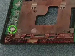
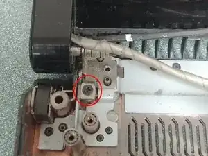
Remove the two phillips screws securing the hinge of the display on both sides of the chassis then lift up on them to remove the display.
-
You’re done (for the most part)! The only things that are left are in plain view such as the charging port and subwoofer and only have one or two unobstructed screws. To reassemble your device, follow these instructions in reverse order.
