Einleitung

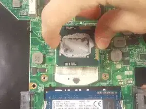
You may want to replace your processor if it has failed or you are looking to upgrade your existing processor to another compatible CPU.

  1. RaGLEEuLoqcXgWIU
    RaGLEEuLoqcXgWIU
    EMwVHdF1HFQWFJlt
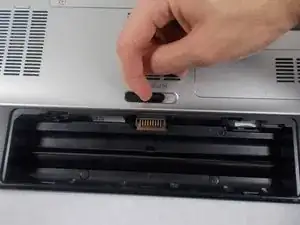
    • Make sure that the laptop is shut off before attempting to remove any components from the device.

    • The laptop in this example did not have a battery equipped.

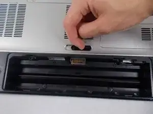
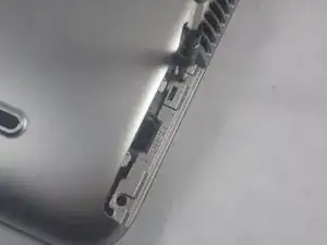
    • Locate the spring latch on the bottom of the device that will unlatch the battery.

    • Hold the spring latch in the open position and pull the battery out of its recess.

  2. dB2Ie2WoYUx15CFD
    dB2Ie2WoYUx15CFD
    G3pOPHHycPToBuki
    DkZ4P1Rq4qplafDH
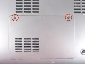
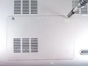
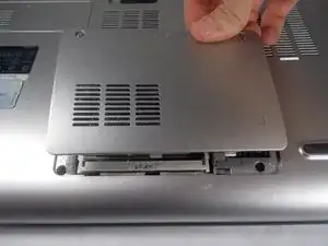
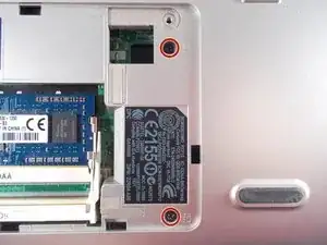
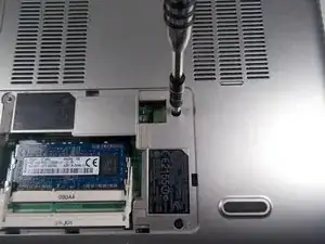
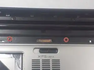
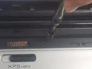
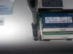
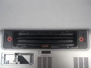
    • Use a JIS 1 screwdriver to loosen the (2) captive screws from the panel.

    • The captive screws will not come off of the panel.

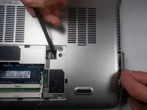
    • Pull the panel upwards and towards the battery to remove.

    • Put the panel to the side, exposing the RAM.

  3. TaZbkkTZ3Gai3Mhs
    TaZbkkTZ3Gai3Mhs
    EHvIFAx4xCyaakbU
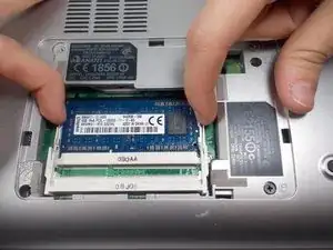
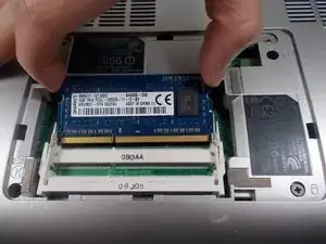
    • The RAM is held by two spring clips. Pull at the two spring clips and the RAM will move upwards.

    • Keep your fingers on the edge of the chip.

    • Only handle the RAM by the sides! Do not touch the circuits or the terminals to avoid contamination!

  4. CXB5mHgbWahM6WwW
    CXB5mHgbWahM6WwW
    xPgnyxDoQJnklbLN
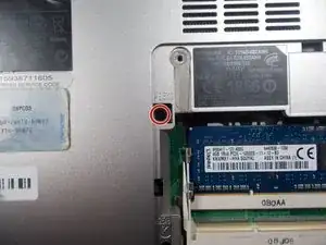
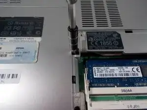
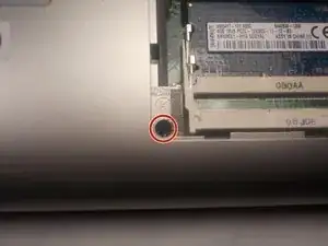
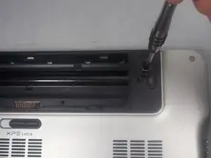
    • Locate and remove (1) 8.5mm JIS 1 screw at the top left corner of the RAM bay.

  5. 4jymuWvylldXQgxJ
    4jymuWvylldXQgxJ
    qRnwDKItVRArtkJs
    3TxbHSCkYGwZnXPL
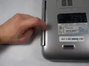
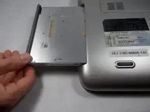
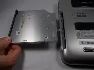
    • Carefully pull out the optical drive from its bay.

  6. M4BCFHNZ5WJfoMox
    M4BCFHNZ5WJfoMox
    Wb1XBHXMA6VTD6A5
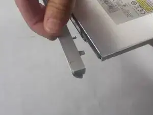
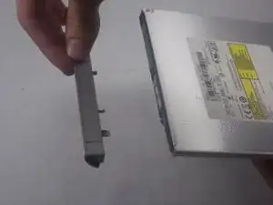
    • Carefully pull off the decorative cover from the front of the optical drive.

    • This decorative cover will be transferred to the new optical drive.

  7. aSsVCuaiodDExgXB
    aSsVCuaiodDExgXB
    NUWUWM2wjiobEBah
    j1HUcQqicNR3uqeq
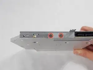
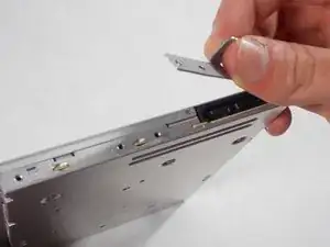
    • Use a JIS 1 screwdriver to remove (2) 2mm screws on the drive's anchoring bracket.

    • This bracket will be transferred to the new optical drive.

  8. QLBYaRmA2RGyjNB2
    QLBYaRmA2RGyjNB2
    JDNspdhatcIlcbhT
    • Use a JIS 1 screwdriver to remove (2) 2.5mm screws located on the right side of the RAM bay.

  9. wIFU6AeknsFSQqho
    wIFU6AeknsFSQqho
    owfJ6fMudkFFFLUw
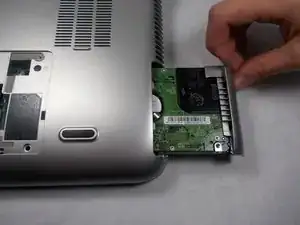
    • Push the hard drive to the right with a spudger to unseat it from its socket while pulling out the hard drive with your other hand.

  10. wvYskFFuVS4OvC3L
    wvYskFFuVS4OvC3L
    EIw6TWCXInX6iBNq
    Q1y1BerAZRmkkdqo
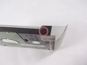
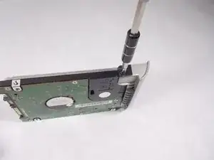
    • Use a JIS 1 screwdriver to remove (1) 2.5mm screw attaching the plastic cosmetic cover to the hard drive.

    • Detach the plastic cosmetic cover from the hard drive.

    • This cosmetic cover will be transferred to the new hard drive.

  11. rhyuPcryCd2eofLT
    rhyuPcryCd2eofLT
    CjqNXdVfaY1pOqKO
    dpxXcdK1IEQXsL5f
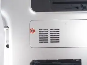
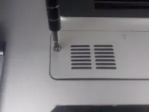
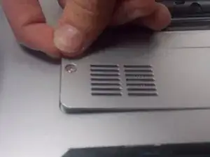
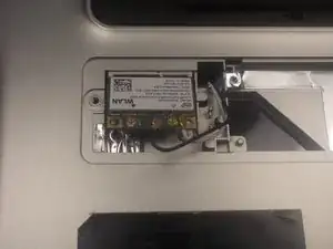
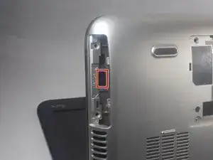
    • Locate the mini card access panel marked with a radio tower emblem on the bottom of the laptop near the battery bay.

    • Use a JIS 1 screwdriver to loosen the captive screw securing the panel to the device.

    • The captive screw will not come off of the panel.

    • Carefully remove the panel by prying it upwards, unlocking it from the tabs that are securing it in place.

  12. NVYVVyADwBJnycq3
    NVYVVyADwBJnycq3
    raGsbum3ZQwO1WDZ
    R1kjOLeCTMHwEDu4
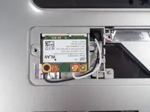
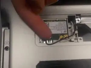
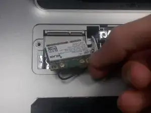
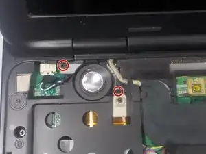
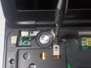
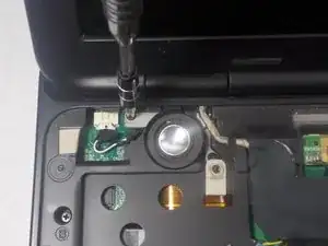
    • Disconnect the two wires on the mini card by carefully plucking them upwards by the metal contact points at the terminals.

    • Do not pluck the contacts off of the terminals by pulling on the wires, this can damage the cables.

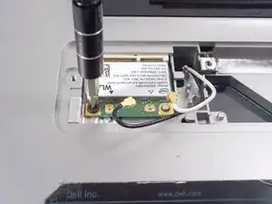
    • Remove (1) 2mm screw from the bottom left corner of the mini card with a JIS 1 screwdriver.

  13. scGbIwrN3XVH2DHB
    scGbIwrN3XVH2DHB
    pjjU5iFmJKZTxSxd
    • Remove the mini card as it flips upward.

  14. 5oVl2DaPcvLewppB
    5oVl2DaPcvLewppB
    3ZWiv6HpJJHCyFxJ
    • Remove two 4.5mm screws with JIS 1 screwdriver marked by the letter "K" in the optical drive bay.

  15. FINEENjGHH5BkimD
    FINEENjGHH5BkimD
    FIZxJvkriNRJs3Wo
    • Remove (2) 4.5mm screws with JIS 1 screwdriver marked by the letter "K"in the hard drive bay.

  16. 1ZHSHW146gCMnm5g
    1ZHSHW146gCMnm5g
    IyoWBQJgeH1m2wAl
    • Remove (2) 4.5mm screws with JIS 1 screwdriver marked by the letter "K" near Battery

  17. bi5ycgAIcwKP1u6D
    bi5ycgAIcwKP1u6D
    VkwWDhRLJlrfGPyy
    • Remove (1) 7.5mm screw with JIS 1 screwdriver marked by the letter "K" in the RAM bay.

  18. SuIZyQEpoIlDKVtr
    SuIZyQEpoIlDKVtr
    Ocn2EKVZiSEiBr4G
    QN4fYw3GnBZYdYkr
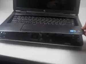
    • Open the display to provide room for the palm rest to come out.

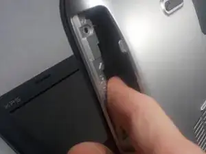
    • In the hard drive bay, push the "push" pad to lift up the palm rest.

  19. yi2WXl3YJKLoTtAC
    yi2WXl3YJKLoTtAC
    ctEyyfCN1EEZY4Ba
    LLaDy4ldHgwseQki
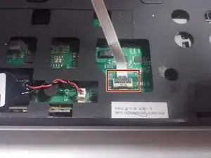
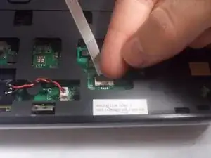
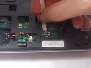
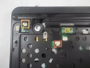
    • Disconnect the track pad cable by flipping up the gray clamp and lifting the cable up.

  20. NjYI46VrZH4KQ2kI
    NjYI46VrZH4KQ2kI
    ZlKfWbcB1JNX6BUX
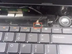
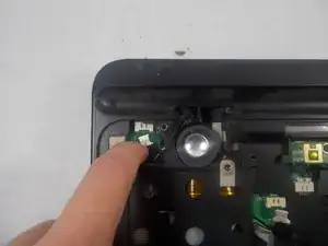
    • Disconnect the status bar cable by pulling the pin connector upward.

    • Finish lifting up the palm rest.

  21. UjSVjYK14xASQSVS
    UjSVjYK14xASQSVS
    gc6jg42mefjyaJsS
    • Use a JIS 1 screwdriver to remove (2) 2.5mm screws located near the top of the keyboard.

  22. e6dqZwVJWFLiPSDu
    e6dqZwVJWFLiPSDu
    ZEDdudN3tURaEKjL
    WYjrfDhLAd4WDm5v
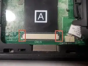
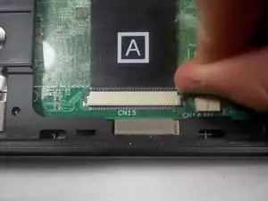
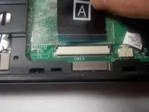
    • Disconnect the keyboard's ribbon cable marked "A" by pushing out the two black tabs towards the ribbon cable.

    • Remove the cable from its connection terminal by sliding it out. Finish lifting up the keyboard and set it to the side.

  23. HFHZVQuEGETABOZN
    HFHZVQuEGETABOZN
    o2CpQrVv5INf6fXo
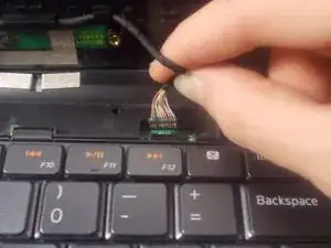
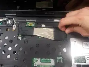
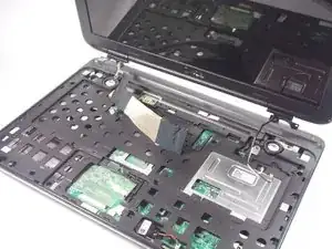
    • Disconnect the display ribbon cable by pulling the cable to the right by its sheathed plastic connector.

  24. homIhPtbWYFeThbS
    homIhPtbWYFeThbS
    scS2wr2iB1BeWrxJ
    YDc5iQoo1qcciorV
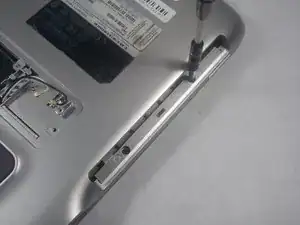
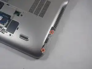
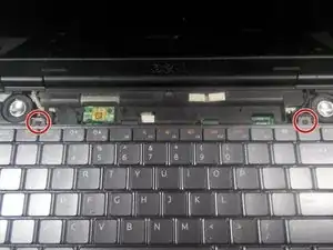
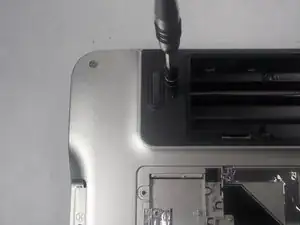
    • Use a JIS 1 screwdriver to remove (2) 7mm screws on the underside of the laptop near the battery bay.

  25. xoBhgb2e5rDX4RFw
    xoBhgb2e5rDX4RFw
    g4NdNPyL1DrOxPRo
    CPmMsm3hUE2BYQRH
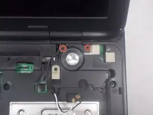
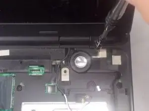
    • Remove (2) 4mm screws with a JIS 1 screwdriver that are holding down the right side display anchor.

    • Be careful not to puncture the speaker membranes with the screwdriver.

  26. HNXxkw6cdhVlcXJU
    HNXxkw6cdhVlcXJU
    xOnPTk6d3QmvCRdL
    hjYMAf1OHNNjtoW5
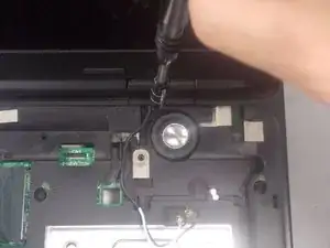
    • Remove (2) 4mm screws with a JIS 1 screwdriver that are holding down the left side display anchor.

  27. O5cxCAJsT6goBWcY
    • Lift the display assembly up and off of the main body of the laptop.

  28. VpbWehUNWUtuxC2Z
    VpbWehUNWUtuxC2Z
    kdwYWAuN5OToIJ5W
    iCUXuxxBCaqlJd5F
    • Disconnect the cooling fan cable.

    • Disconnect the speaker power cable.

  29. aQUUICDyFFnYhhj1
    aQUUICDyFFnYhhj1
    K4DDsLGER1LKOCDt
    ZGIIhwmURYKcv5an
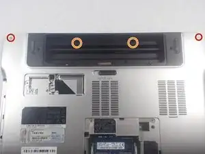
    • Remove (2) 15 mm screws located on top left and right corners on either side of the battery bay using a JIS 1 screwdriver.

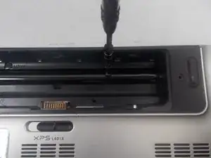
    • Remove (2) 2mm screws located in the battery bay using a JIS 1 screwdriver.

  30. nliSopcXryEaoVuY
    nliSopcXryEaoVuY
    EIXJoIFwnZuNGpPK
    • Flip the laptop over.

    • Remove (8) 4mm screws marked with the letter "B" with a JIS 1 screwdriver.

    • Remove (1) 7mm screw marked with the letter "B" with a JIS 1 screwdriver.

  31. cdMTossQgGwqAbAT
    cdMTossQgGwqAbAT
    FtNSuAZwdm1SWkBX
    Q2WatT5EDrLpbdlU
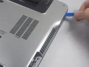
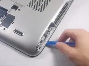
    • Separate the bottom cover from the top cover with plastic prying tool and finish lifting the bottom cover off.

  32. hWtAKBcCT3J3BjYH
    hWtAKBcCT3J3BjYH
    lEaZgAHrQMj16SxV
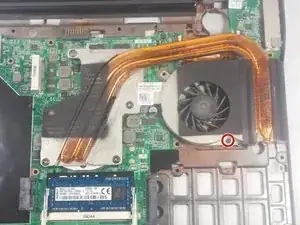
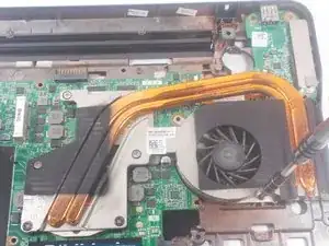
    • Use a JIS 1 screwdriver to remove (1) 4mm screw on the cooling fan assembly.

    I need cooling fan to be replaced to my laptop

    Jithender Keluth -

  33. olHl42IgHgDresKe
    olHl42IgHgDresKe
    DhDxZnLlr6Gw2mMC
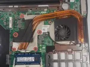
    • Locate the (5) captive screws that hold down the heat sink assembly to the central processing unit and the graphics processing unit.

    • The captive screws are marked 1-5 in consecutive order, and they will not come off of the heat sink when loosened.

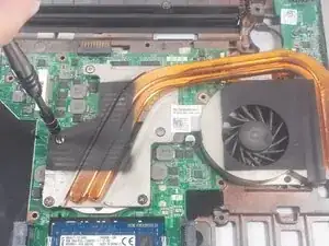
    • Unscrew captive screw #1 with a JIS 1 screwdriver for one or two turns and move onto the next screw (#2) and so on, in consecutive order.

    • Continue to slowly loop around the 5 captive screws in order, only loosening the screws one or two turns each time until all screws are completely retracted.

    • Do not loosen any captive screw fully without moving to the other screws first! This can bend the heat sink assembly and possibly damage the processors.

  34. 22PApixJdEUOxG4y
    22PApixJdEUOxG4y
    dWgql1EG54qkvCpt
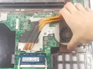
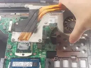
    • Carefully pull the heat sink assembly upwards off of the motherboard after all the captive screws have been loosened fully.

    • Clean off any existing thermal paste from the mating surfaces (CPU, GPU, and the heat-sink itself) and apply new thermal paste, before putting the heat sink back on later.

  35. LjIgKWnbkPltfoEF
    LjIgKWnbkPltfoEF
    MKIcTLETXtWcqNKJ
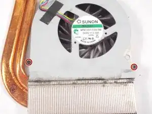
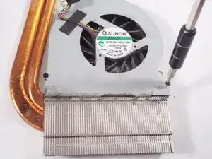
    • Remove (2) 2mm screws on the sides of the cooling fan with a #00 Phillips screwdriver.

  36. KCkDSfDvX4fBWieX
    KCkDSfDvX4fBWieX
    tSALulF25lioACF1
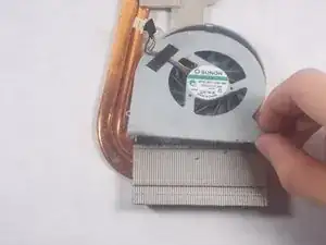
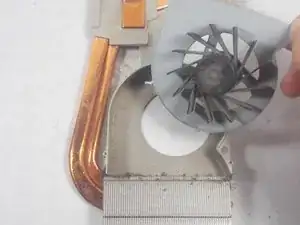
    • Remove the cooling fan from the heat sink assembly by pulling it upward.

  37. Wnr6mBYMmWYBP2J3
    Wnr6mBYMmWYBP2J3
    GLswDaGlVNBUviHH
    vfSGk1S5ZPJZHjxr
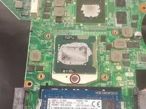
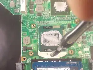
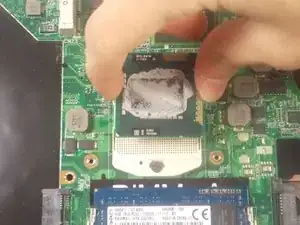
    • Locate the CPU locking screw on the processor socket.

    • Use a #4 Flathead screwdriver and turn the locking screw counter-clockwise until it stops.

    • Lift the processor out of its socket carefully to avoid damaging the pins underneath.

    • Only handle the processor by the sides of the component to avoid contaminating or damaging it.

Abschluss

To reassemble your device, follow these instructions in reverse order.
Mark

Mitglied seit: 19/10/17

643 Reputation

0 Kommentare