Einleitung

Use this guide to remove or replace the control/connecting rod on the pump for a Dewalt Air Compressor DWFP55126 2016.

Make sure to completely depressurize the air compressor tank before performing any repairs.

  1. x5EDdZylNX6j2MgJ
    x5EDdZylNX6j2MgJ
    OeDIS4lEeM2aP2BC
    qS1526i2EmvMyFKr
    • Disconnect the power cord, depressurize the compressor tank, and remove any hoses before starting this repair.

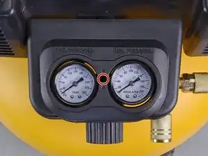
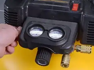
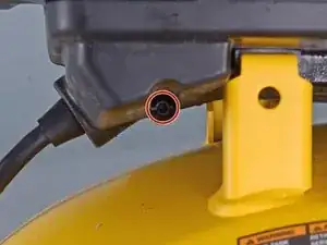
    • Use a long-shank T10 driver to remove the manifold cover screw.

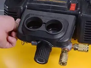
    • Lift the cover directly up off of the gauges to remove.

  2. w6Vnn16TCS5Z4U2w
    w6Vnn16TCS5Z4U2w
    BvINyKYx2PW1lCRO
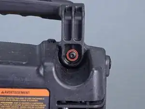
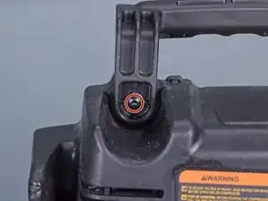
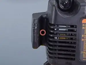
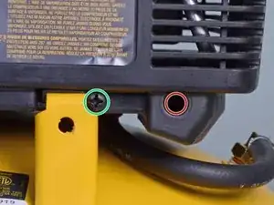
    • Use a T20 driver to remove the two handle screws, one on each side.

  3. CVjsDNDUK5oLdgTj
    CVjsDNDUK5oLdgTj
    nooQj3FfjBh1isZM
    gVmq5sZmQDDKRkMK
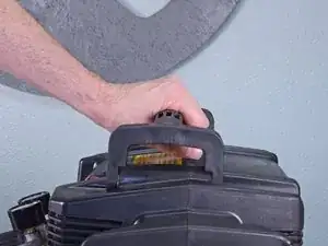
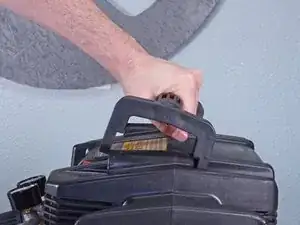
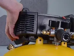
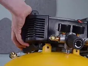
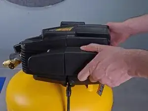
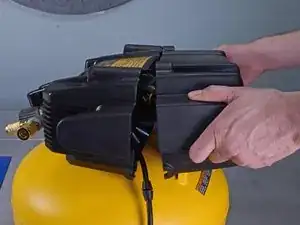
    • Grab the handle like you would if you were to pick the compressor up. Pull up and push forward away from the gauges at the same time to rotate the handle up off the case.

    • Lift the handle off to remove.

  4. eGuiUtru2SRyRRNZ
    eGuiUtru2SRyRRNZ
    FrM3ODRKARPcNIJO
    yqhHPel1EtenYcBI
    • Remove the following four screws:

    • Three 20 mm-long T20 screws.

    • One 20 mm-long Phillips #1 screw.

  5. Hriu4obOvKJKqcdZ
    Hriu4obOvKJKqcdZ
    V12SlHHhA4bJQevy
    • Four metal tabs on the tank sit in four slots on the top plastic case to secure the case to the tank.

    • Firmly push the top case off of the four tabs to detach.

  6. PEjb3KkqsTAtS61W
    PEjb3KkqsTAtS61W
    O1LeYJoYS1XDDwBi
    tSZitvWBPINCRmVp
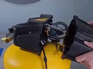
    • Carefully pull the half of the case that is opposite the manifold away from the tank.

    • The motor may shift once the case is removed, but it won't fall out.

    • Reassembly tip: align the power cord in the cord cutout so it doesn't get pinched.

  7. t2ySJYVm1dD6FdSE
    t2ySJYVm1dD6FdSE
    MFFV1QDcqZgfYGB4
    cqbCuDR1y3Ry2hwG
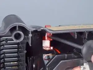
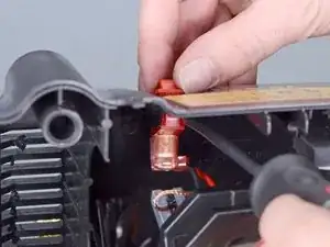
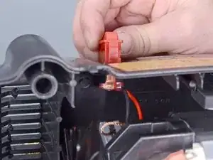
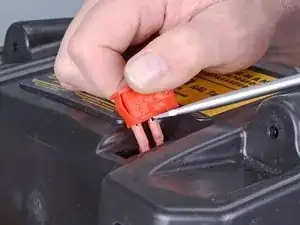
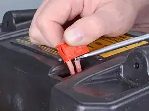
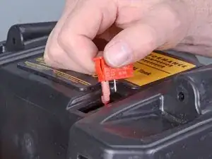
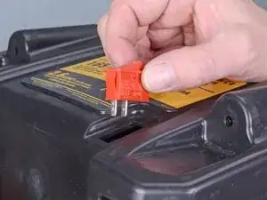
    • Use a large flathead screwdriver to depress the plastic tab on the red power switch closest to the open side of the case.

    • While keeping the tab depressed, grab the top side of the switch and pull directly up off the case.

    • Pull the switch farther out of the case.

    • Don't try to completely remove the switch; there are still wires attached below.

  8. 5QdGZsHyrX5f1jYy
    5QdGZsHyrX5f1jYy
    FtAWMsoEQ6SKWmar
    • Use a flathead screwdriver to pry both wire connectors slightly off the plugs on the bottom of the switch.

  9. AfaGgjUF4XEJYySm
    AfaGgjUF4XEJYySm
    ij1YQQUmYXreqbsB
    • Once the wires are loosened from the plugs on the switch, completely remove both wires.

    • Remove the power switch.

  10. xwlfKBDGjSC4OVnv
    xwlfKBDGjSC4OVnv
    ePcEceSmHyAUpTFb
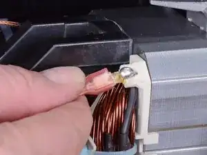
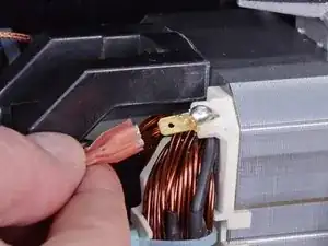
    • Carefully pull to remove the connector on the ground wire located inside the case.

  11. MotgOpBJVqBEu64I
    MotgOpBJVqBEu64I
    HtviHTmKuyuQHCJp
    HaH2dl6QcfO1XxiM
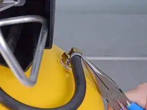
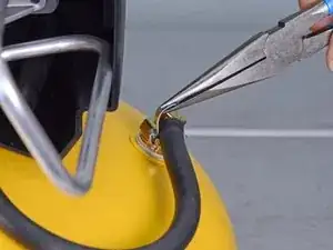
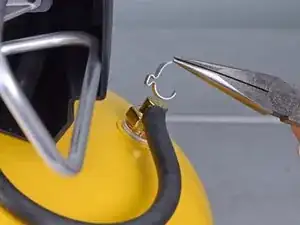
    • Use needle nose pliers to bend the check valve hose clamp up away from the hose.

    • Once the hose clamp is bent enough to clear the hose, lift it up and off to remove.

    • We strongly suggest you replace this hose clamp during reassembly to prevent leaks during operation.

  12. FWK45DyH3I2VXEcj
    FWK45DyH3I2VXEcj
    vNkSuuiDuaLG24bl
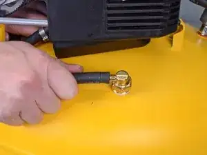
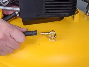
    • Pull the hose off the fitting to remove.

  13. nGSOPj5GP1hYOTrg
    nGSOPj5GP1hYOTrg
    2trJDecPHNjbNU1K
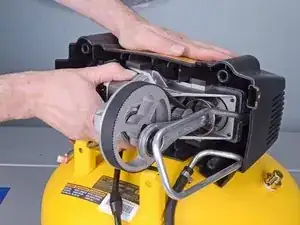
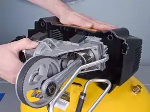
    • While holding the plastic housing, pull the pump assembly out, careful to not snag hoses or wires.

  14. PMSwB1AQO4yYOrgH
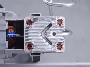
    • Use a 5/8 inch socket to remove the four cylinder head bolts.

  15. CRQyoNu52XYnIKA4
    CRQyoNu52XYnIKA4
    AAbpI3soqnvRHDNP
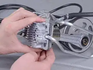
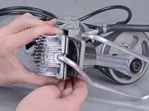
    • Pull the cylinder head off of the pump assembly.

    • The cylinder head gaskets can be very sharp around the edges. Wear gloves if you need to.

  16. I2BJvl4nXbUqYdoF
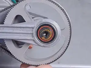
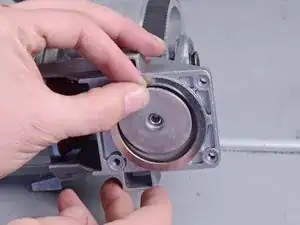
    • Use a T45 driver to remove the control rod bolt.

  17. dlSc3oOjtUCgoq6G
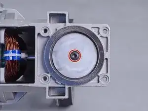
    • Use a T20 driver to remove the piston screw.

  18. SDPbmLQc1QQXbBsl
    SDPbmLQc1QQXbBsl
    sNYI1HyQyOsHmZVf
    uxxqZNGHSZCTc2JS
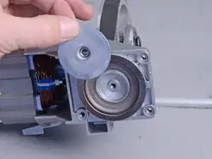
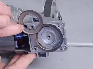
    • Remove the top piston plate.

    • Remove the piston washer.

  19. RsfILsIVJJCKKsJr
    RsfILsIVJJCKKsJr
    WuS5IsDgaSMffOs1
    qI2IVOJq2M4TdMMc
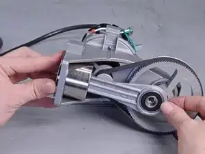
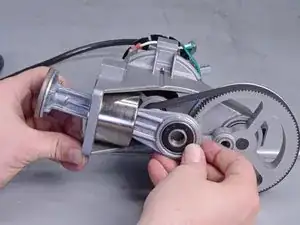
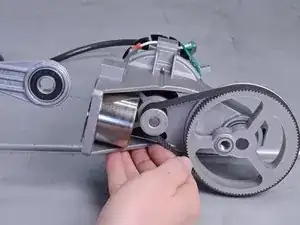
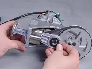
    • While holding the metal cylinder wall in place, push the control rod out to remove.

  20. lmCmGuKPRmWTRhdx
    lmCmGuKPRmWTRhdx
    jj11FEwhy5RcxbZH
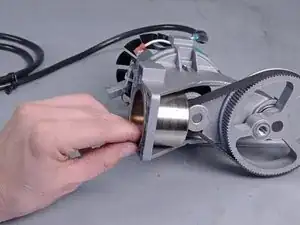
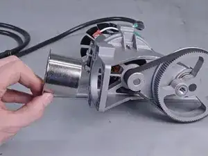
    • Remove the cylinder wall.

    • A new cylinder wall is included in the new control rod assembly.

Abschluss

To reassemble your device, follow these instructions in reverse order.
Carsten Frauenheim

Mitglied seit: 10/03/20

88317 Reputation

0 Kommentare