-
-
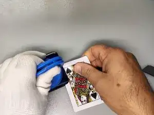
Worm the device to soften the adhesive.
-
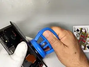
Use Sanction cup, Plastic tools and isopropyl alcohol.
-
Remove the silver Phillips screws from the middle frame.
-
-
-
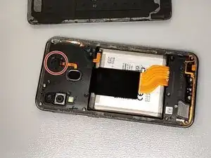
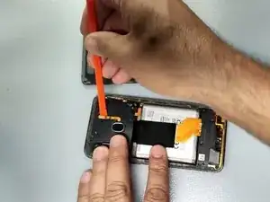
Remove the plastic cap from the Fingerprint flex cable connector and disconnect the cable.
-
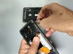
Remove the SIM Tray.
-
-
-
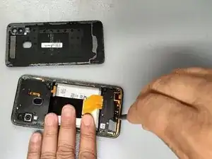
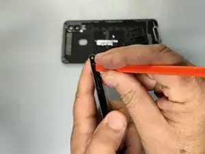
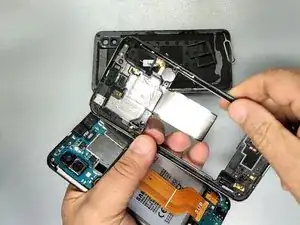
''Use plastic tool to separate the middle frame. Start from the SIM Tray hole.'
-
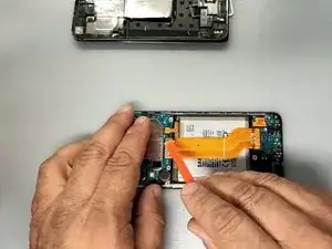
First of all disconnect the battery.
-
-
-
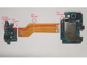
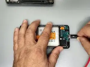
Disconnect the Main flex cable and connect the charger.
-
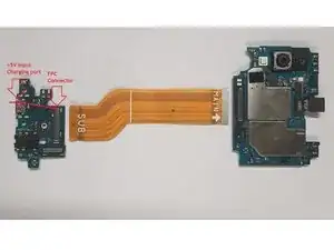
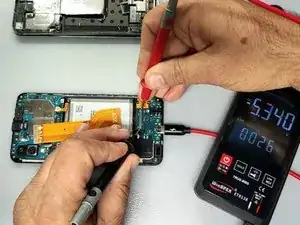
Use a multimeter to measure the voltages at the the large end pins of the FPC connector of the Charging board (See the second image)
-
If the reading is okay (~5V) continue with the next step, if not - change the Charging board.
-
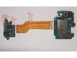
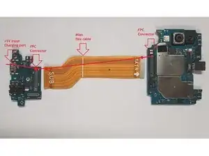
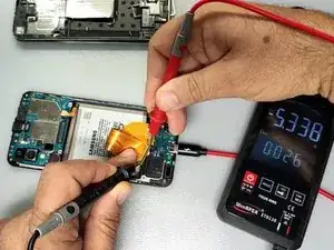
Attach the Main flex cable and measure the large end pins of the Main flex FPC connector - pic.3.
-
If the reading is okay, continue with the next step, if not - change the Main flex cable.
-
-
-
Remove the adhesive rubber.
-
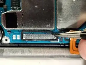
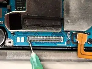
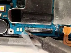
Use some flux and soldering iron to re-solder the first pin of the Mother board FPC.
-
To reassemble your device, follow these instructions in reverse order.
