Einleitung
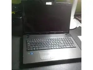
Maintenance is an extremely important aspect of using a laptop. This guide will demonstrate how to disassemble the Acer Aspire 7551G for the purposes of cleaning, upgrading, or part replacement.
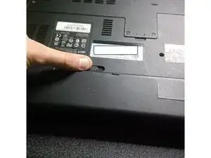
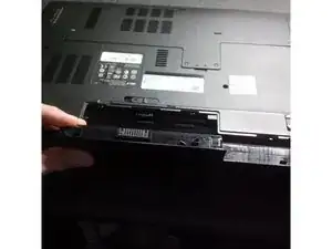
Before the start of the disassembly process, make sure to disconnect the laptop from its power supply and place the device on a flat work surface with plenty of space around it to avoid mishandling the delicate components.
Werkzeuge
-
-
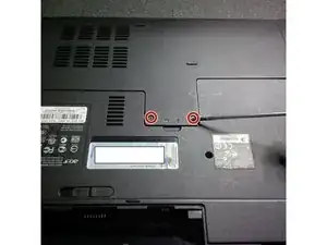
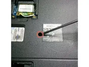
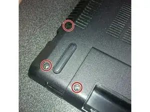
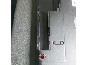
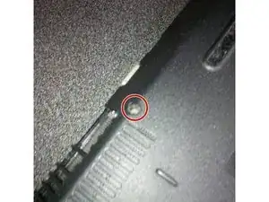
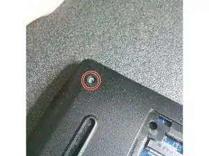
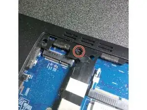
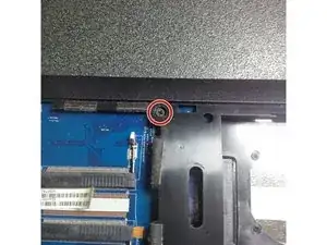
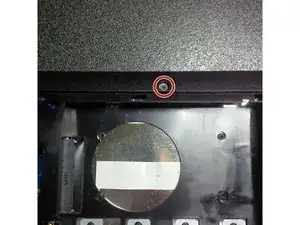
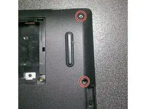
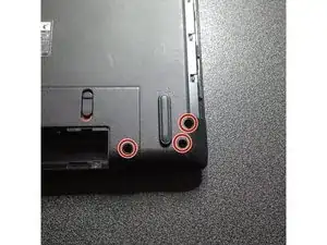
Use Phillips #000 Screwdriver to remove the case holding screws, remove the 4 screws that hold the back panel.
-
-
-
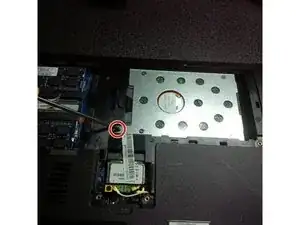
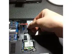
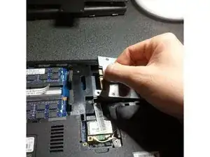
To remove the hard drive, undo the screw that holds it in place and carefully pull the HDD to the right.
-
-
-
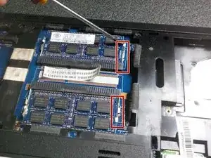
To remove the RAM modules just click the metal levers to the right.
-
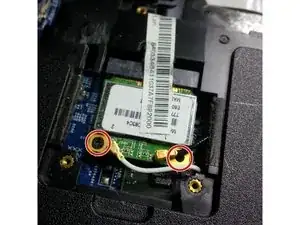
Remove two black screws from the WiFi card.
-
-
-
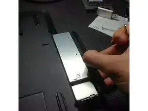
Using the Phillips #000 Screwdriver remove the screw that hold the DVD bay in place.
-
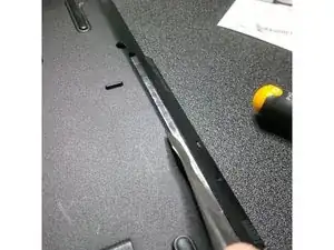
Use a spudger to pry the DVD bay away from the case.
-
-
-
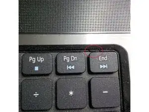
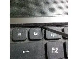
To remove the keyboard, pop the three latches away from the keyboard with a spudger.
-
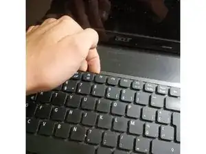
Gently pull the keyboard from the laptop, but be careful not to damage a flex cable that connect it to the motherboard.
-
-
-
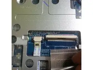
Move the flex cable away from the keyboard.
-
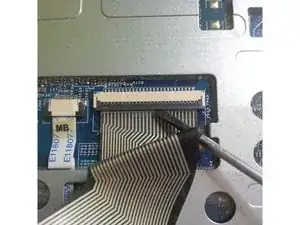
Place a Flathead screwdriver under the head of the cable and pry it upwards.
-
-
-
Use the IC Extractor/Connector Puller to remove the cables.
-
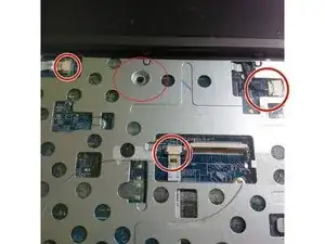
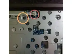
Use the Phillips #000 Screwdriver to remove the frame screws.
-
-
-
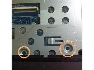
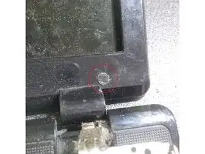
Remove all black plastic stickers to reveal the hidden screws.
-
Use Phillips #000 Screwdriver to remove the hidden screws.
-
Remove the cable from the webcam module
-
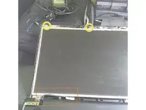
Remove the screws that hold the screen to the inner frame.
-
-
-
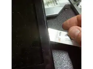
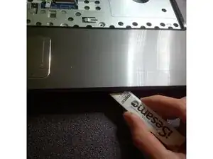
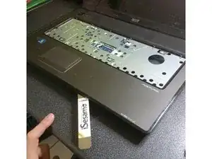
Use the iSesamo Opening Tool to pry under the outer edge of the laptop body.
-
After hearing the first click, move the tool around the perimeter until all of the clips are undone.
-
After the clips are undone, remove the back cover.
-
-
-
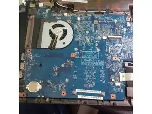
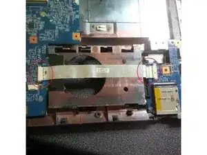
Carefully remove the ribbon cable connecting the two halves of the motherboard.
-
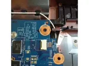
Use Phillips #000 Screwdriver to remove the motherboard screws.
-
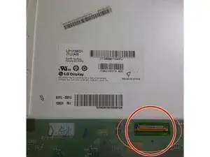
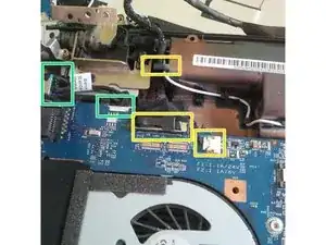
Use a plastic prybar to remove the LCD connector. Be careful not to break the cable or its plastic holder.
-
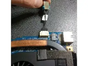
Unplug the DC jack cable before removing the motherboard.
-
-
-
Remove the disconnected DC jack from its holder.
-
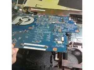
Carefully lift the motherboard out of the case.
-
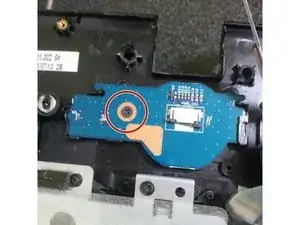
Use Phillips #000 Screwdriver to remove the screw that is holding the power PCB.
-
-
-
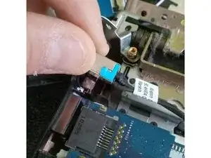
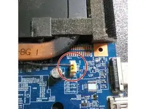
If the replacement of the DC jack is necessary, use the IC Extractor/Connector Puller to safely unplug the connection.
-
-
-
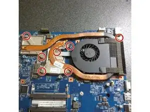
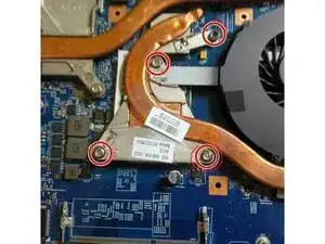
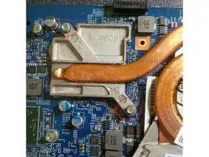
Use the Phillips #000 Screwdriver to remove the cooling pad screws.
-
Lift the cooling pads and the fan assembly.
-
Remove the old thermal compound, degrease the surface with rubbing alcohol.
-
Use a can of compressed air to clean the fan assembly.
-
To reassemble your device, follow these instructions in reverse order.
