Einleitung
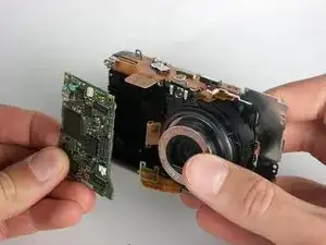
The logic board is the brains behind the camera and should be handled delicately.
Werkzeuge
-
-
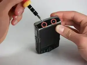
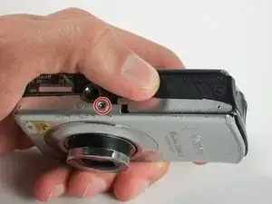
Remove the two 2.4 mm screws on the side of the camera that are next to the LCD screen using a Phillips #00 screwdriver.
-
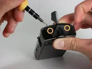
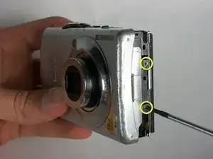
Remove the two 4.1 mm screws on the other side using a Phillips #00 screwdriver.
-
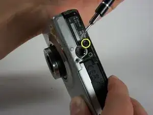
Remove the single 2.6 mm screw from the bottom of the camera using a Phillips #00 screwdriver.
-
Slowly pull the back cover off of the camera.
-
-
-
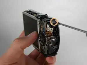
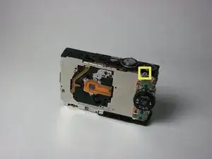
Remove the 2.6 mm screw from the bottom of the camera using a Phillips #00 screwdriver.
-
Remove the 4.1 mm screw from the menu button side of the camera using a Phillips #00 screwdriver.
-
-
-
Unplug the green and white plugs that connect the top panel to the top of the logic board.
-
Dislodge the tab above the lens.
-
Dislodge the tab at the back.
-
-
-
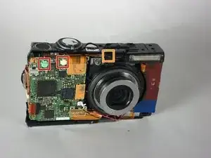
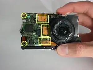
Remove 2 screws(1.75mm) using a screwdriver.
-
Detach 3 ribbons by pulling up on them. All are on the front of the camera.
-
-
-
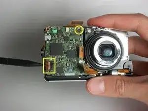
Remove the newly exposed screw(1.75mm) with screwdriver.
-
Unhinge the black tab to slide out the ribbon.
-
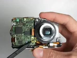
The only thing keeping logic board in place is a black nub. Lift the logic board from that corner with increasing force until it pops out.
-
To reassemble your device, follow these instructions in reverse order.