Einleitung

  1. MQcjYMC6BnKBoYJt
    MQcjYMC6BnKBoYJt
    Je5rXV1Adi2DhA3x
    ntTTFlKZdWoVP25E
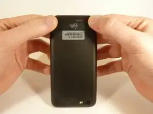
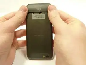
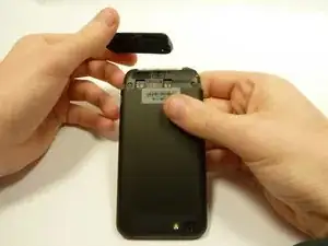
    • Power off your device.

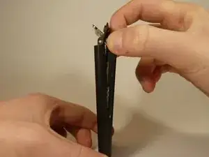
    • Remove the bottom cover by sliding it off.

  2. kJDBcsdtUC2GEqOH
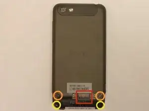
    • Remove the SIM card.

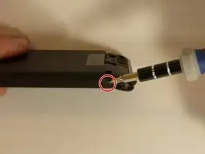
    • Remove the four screws securing the bottom casing.

    • Two 3.0 mm Phillips #0 screws in the top left and right corners.

    • Two 2.0 mm Phillips #0 screws in the bottom left and right corners.

  3. aSeFyHbjrXBMfKQH
    aSeFyHbjrXBMfKQH
    tQDmkjC4yOjsn1ZJ
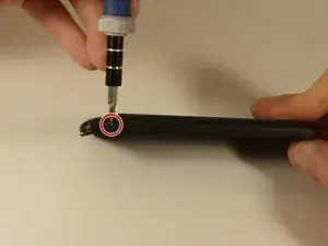
    • Remove the 2.0 mm Phillips #0 screws on either side of the phone.

  4. HlnZGN56qE63SXKS
    HlnZGN56qE63SXKS
    HBDceTc5AMKMnHqn
    GohLHKBevSHkOWHx
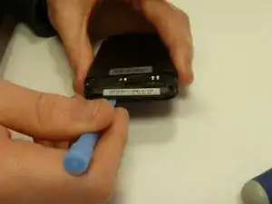
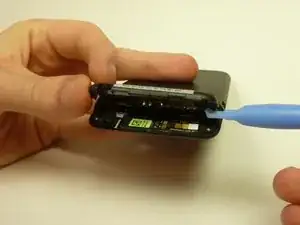
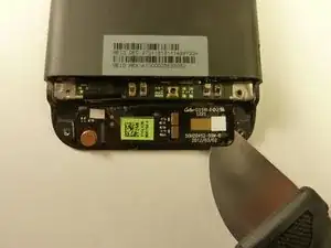
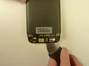
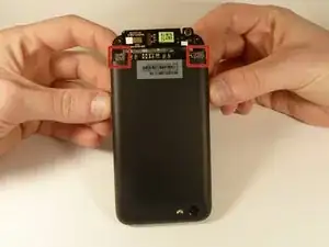
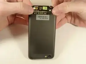
    • Use a plastic opening tool to pry open the bottom casing.

    • Remove the bottom casing by pulling it towards you.

  5. BCBtgQ3PeHYVN3lU
    BCBtgQ3PeHYVN3lU
    strOZm3ORoIJdYOP
    xpOnG4oSLFQNLD5h
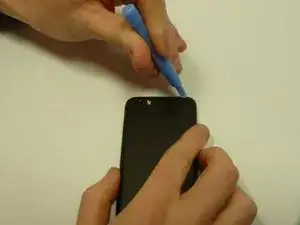
    • Use the plastic opening tool to pry open the rear camera panel.

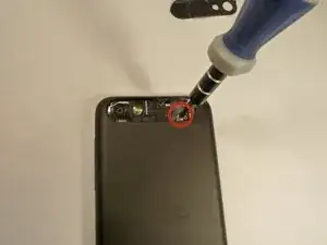
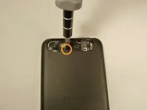
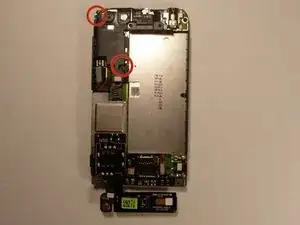
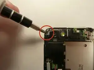
    • Remove both screws that are securing the back case.

    • One 4.0 mm Phillips #0 screw.

    • One 3.0 mm Phillips #0 screw.

  6. ps4lSXAv5MLAFcTe
    ps4lSXAv5MLAFcTe
    5m2gUGiKKVfWtnyK
    AYHAOP4VhZSbEcPm
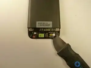
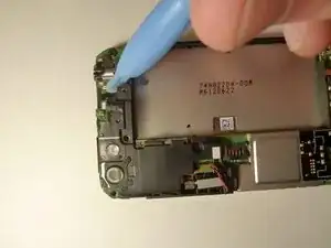
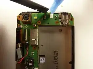
    • Use a Jimmy to pry up the OEM SIM and SD card reader contact.

    • Pry from right to left to avoid potential damages to the ribbon.

  7. sCDyFjtG5pSLaSCx
    sCDyFjtG5pSLaSCx
    dsNPQlBpvCXJfUH4
    2PFGLLvetMPLQEac
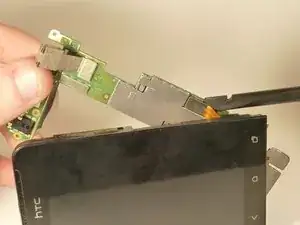
    • Using both thumbs, gently push on the two bottom rear corners of the motherboard.

    • Gently and slowly pull the screen out from the front of the phone, while feeding the OEM reader contact through the opening.

  8. NRACgCMDbwx5gO6o
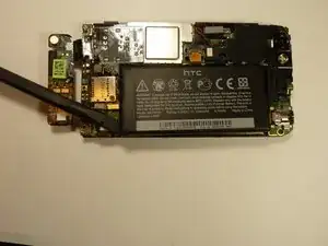
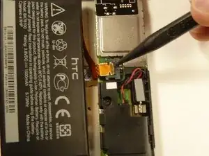
    • Pry up the battery with the flat end of the spudger.

  9. dQoOUQpOlvvfnp5P
    dQoOUQpOlvvfnp5P
    xaaQby2xE1bZP3vE
    lQFjPYM2WAuR6322
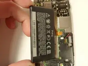
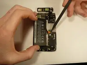
    • Gently lift up the battery away from the edge of its housing.

    • Use the point end of the spudger to push the connection out of its housing.

  10. 425sZZUIARFp3JXU
    425sZZUIARFp3JXU
    F3XI2wP2Kf63tVZF
    nLUrBFXWTyytaoHc
    • Remove the two 3.0 mm Phillips #0 screws, that are securing the camera lens.

  11. Qb2Z4CZGJC5UARqW
    • Pry off the camera lens using a plastic opening tool.

  12. w5bMFmITUFYjwIls
    w5bMFmITUFYjwIls
    YXpsMTQQqycqsZaJ
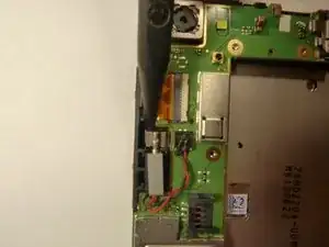
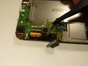
    • Pry the vibrator out of the housing with a spudger.

    • Using the tweezers, pull up on the connecting wires detaching the vibrator from the motherboard.

  13. FWdehyMhrKEmK2rd
    FWdehyMhrKEmK2rd
    4g3eZrBwd2OuEcUI
    MktUFe6bPXnMfk3J
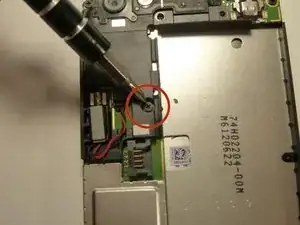
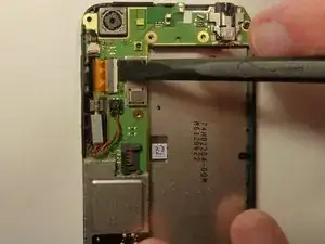
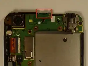
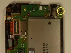
    • Using the spudger lift the tabs on the highlighted, red and orange, ribbon connectors. Gently pull out the ribbons from their connectors.

    • Remove the 3.0 mm Phillips #0 screw.

  14. gCMQBGNeSnaCS4r5
    gCMQBGNeSnaCS4r5
    qUt4jyG2ZkJCBweQ
    ronotG6rhhnWOMET
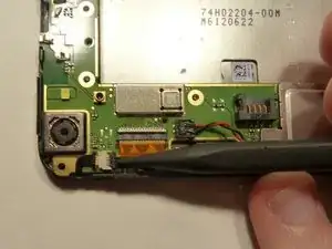
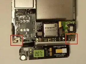
    • Using tweezers, pull back on the tape located on the bottom corners of the motherboard.

  15. 51P4xURkfhs3wZOV
    51P4xURkfhs3wZOV
    XTDSZ2lxFQmJYOO4
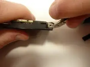
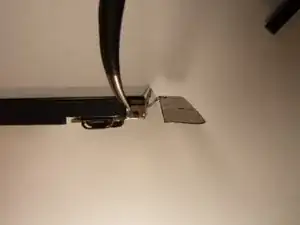
    • Use the spudger to push back the latch holding on the motherboard. While the latch is pushed back use the plastic opening tool to pry up the motherboard.

  16. gWPHE5LExmpqq52C
    • Place your phone on its side so that you can gently pull up on the motherboard to expose its last connector.

    • Using the flat end of the spudger, pop of the connector.

Abschluss

To reassemble your device, follow these instructions in reverse order.
Joshua Rhoden

Mitglied seit: 27/01/15

250 Reputation

0 Kommentare