Einleitung

In this step-by-step guide, you will be removing the speakers from the Thinkpad A30 for replacement.

  1. LojZOTKUVLIFLI2V
    LojZOTKUVLIFLI2V
    KFTIp3x1sSkAhvjA
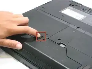
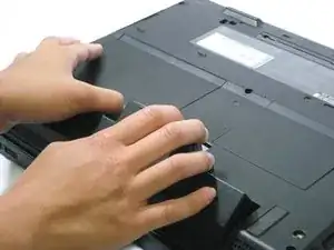
    • Flip the ThinkPad over so that it is upside down.

    • Slide the highlighted tab to the left.

    • With your finger on the tab, remove the battery by lifting it upwards away from the laptop.

  2. YOHHnmoUkp6IKeAD
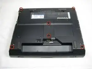
    • Make sure the laptop is upside down and oriented in the direction shown.

    • Remove the six 16.7mm screws inside the circled holes.

  3. qliMGVEk1rnii4pJ
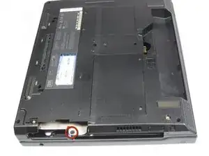
    • Rotate the ThinkPad so that the hard drive bay is facing you.

    • Remove the black cover to reveal a 14.8mm screw.

    • Remove the uncovered screw with a Phillips #0 screwdriver.

  4. awqZ6OGMIVsXTpMb
    awqZ6OGMIVsXTpMb
    1236sEeEkudw3oEe
    • Flip the ThinkPad over and open the LCD panel.

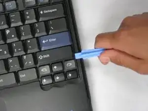
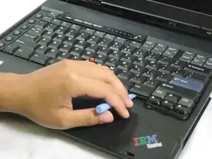
    • Pry apart the keyboard with a plastic opening tool or with your fingers.

  5. hUMMD54OTLkMWaSi
    hUMMD54OTLkMWaSi
    SCNi2HOLe35w2NaV
    WROPmyH6dVkwiNYs
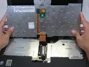
    • Be careful not to pull out the keyboard carelessly; there is a connector underneath it!

    • Lift the front end of the keyboard as shown.

    • Using your fingers, remove the black film cover.

  6. JNGGRLeT4B5NOSvE
    JNGGRLeT4B5NOSvE
    QDRX4UdkIxskLUcq
    BNmkH25bWPQAFhYb
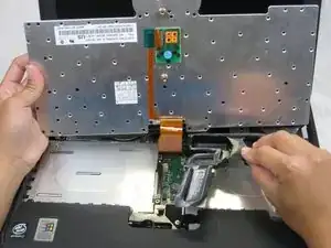
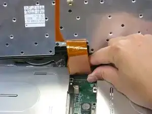
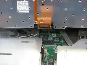
    • Locate the connector attached to the motherboard.

    • Disconnect the ribbon cable by removing the connector.

  7. yH3neYDbx3FGEOvr
    yH3neYDbx3FGEOvr
    o1KTFP6BQJMk1VKL
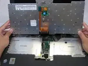
    • Lift and remove the keyboard.

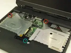
    • Remove the two 5.6mm screws.

    • Remove the 16.7mm screw.

  8. i3uvoJibxsyAXLQv
    i3uvoJibxsyAXLQv
    fCqxglA1KGNANkJX
    LWTgV5OwEshOiZMk
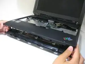
    • You will need to use a little force. Be wary of the tabs.

    • Pry off the upper case with your hands.

  9. Rvnw2xiXDZGMSXXL
    • Remove the 5.6mm screw that holds the LCD to the upper case.

  10. FMFULPfdXbOIK5Qg
    FMFULPfdXbOIK5Qg
    Y5HJpKREZDHLILRf
    RUIHuj2mdkF1ixRo
    • Remove the 5.6mm screw on the left side of the three-pronged connector.

    • Remove the other two 16.7mm screws.

    • Lift and remove connector.

  11. ZWYKKdCxr1pOvEN1
    ZWYKKdCxr1pOvEN1
    iTbIcOsJUZnuyPj4
    • Pull out the white tab connecting the LCD to the motherboard.

  12. rm25WRrrSQ1VNjNi
    rm25WRrrSQ1VNjNi
    pCfenvkHOX1ZSCPC
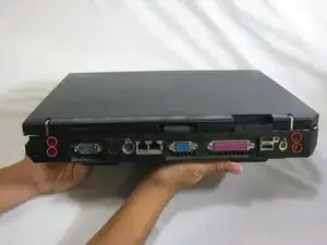
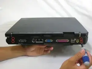
    • Turn the laptop so that the back is facing you.

    • Remove the four 5.6mm long screws.

  13. qtdUNKD6OctdSRmx
    qtdUNKD6OctdSRmx
    JxDXRHsKa2Pb5oca
    lLRj1fPdf1hqqUKF
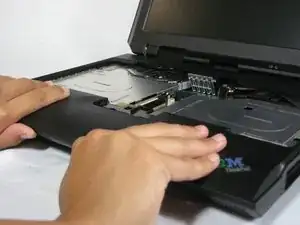
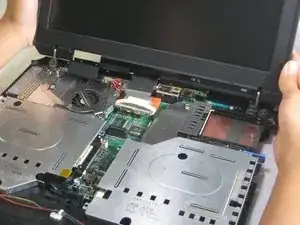
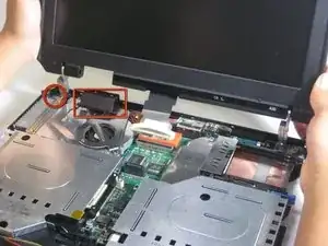
    • Place the laptop so that the LCD is facing you again.

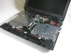
    • Gently lift the LCD monitor up and out.

    • Remove the black plastic tab.

  14. ZaYH3TMhFpHIjmXX
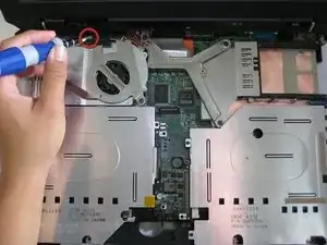
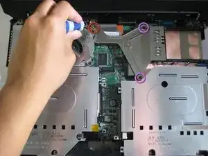
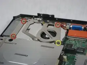
    • Locate the 4 screws that will need to be removed.

    • One screw (yellow) is noticeable. The three other screws (red) are below the heatsink bracket.

    • Remove the 5.6mm (yellow) and three 16.1mm (red) screws.

  15. KpFkTrPmvUNvnJoU
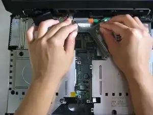
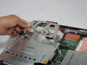
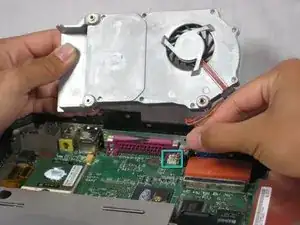
    • Lift the heatsink bracket up.

  16. hdTUuXEcxBGJPuvp
    hdTUuXEcxBGJPuvp
    uUDCOCREnaQgEufT
    VlBShwfTTq2pR2XE
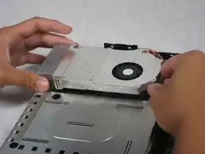
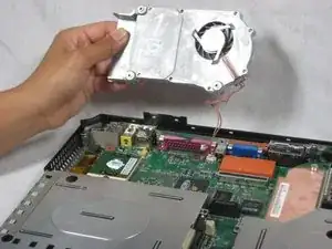
    • Be careful not to pull too hard! There is a cable attached to the fan!

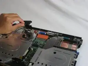
    • Lift the fan/heatsink assembly up.

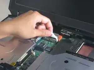
    • Locate the fan power cable and pull upwards near the connector.

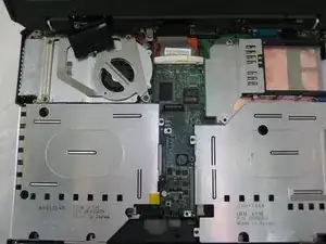
    • Remove the fan/heatsink assembly.

  17. EpZMFYdYRPLRWiZu
    • Locate the floppy drive bay.

    • Remove the four 5.6mm screws.

    • Remove the 16mm screw.

  18. oqneOl6DAcX3Rh3c
    oqneOl6DAcX3Rh3c
    KPXB31myHOidJZJS
    RGdhVCVbmDYVXBE3
    • Turn the laptop over so the battery is facing you.

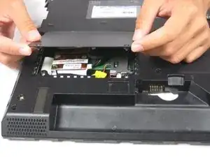
    • Locate the modem and ethernet card bay.

    • Remove the two 5.3mm cover screws.

    • Gently lift the cover.

  19. D1HAUvAkIxjCM4AO
    D1HAUvAkIxjCM4AO
    lRWXruYGjUDam2Mp
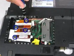
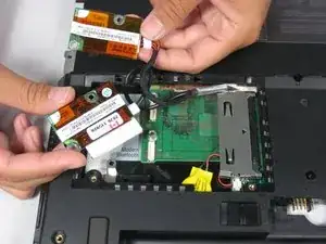
    • Remove the four 9.1mm screws attached to the modem and ethernet cards.

    • When lifting the cards, be careful not to rip out the cables!

    • Gently lift the modem and ethernet cards.

  20. Kg1YUvowofWu3kAW
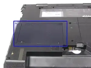
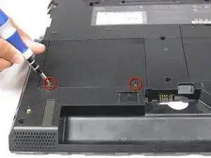
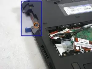
    • Locate the hard drive slot.

    • Remove the 8.8mm screw with a Phillips #0 screwdriver.

  21. xFphCPIXPcdnRQS2
    • Turn the laptop over again and orient it as shown.

    • Lift the left side of the floppy disk bay and and pull it out.

    • The black lever will pop out.

  22. DZAtKP2ItCpErwFi
    DZAtKP2ItCpErwFi
    iMf2rSdFuLN3Btxj
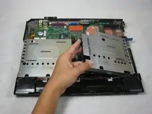
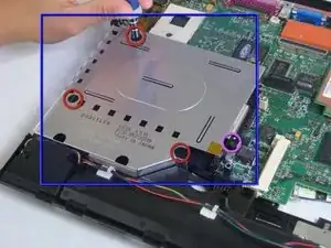
    • Locate the CD Drive Bay

    • Remove the three 5.6mm screws.

    • Remove the 16mm screw.

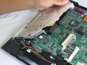
    • Lift the right side and pull the CD drive bay out.

    • The black lever will pop out.

  23. MeIlNLFZMpI2VsZU
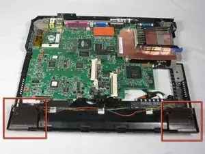
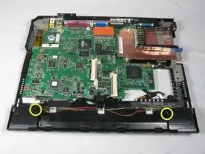
    • Locate the speakers on the bottom left and right of the ThinkPad A30.

  24. KHbmDKCrQMTHH6bI
    KHbmDKCrQMTHH6bI
    iv4DiXQBVXiGVIRN
    sMHTSvvxxmBVNX1I
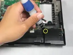
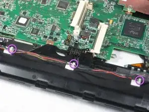
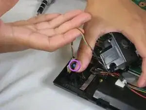
    • Remove the 5.6mm screws on each speaker.

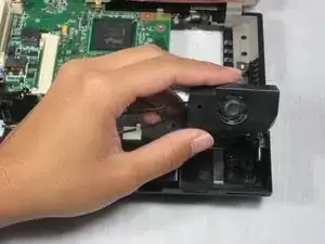
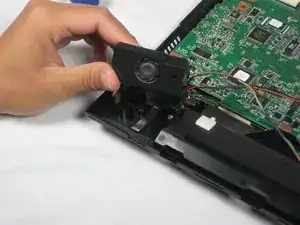
    • Pull the right speaker out, making sure there is still slack in the wire.

  25. LmPnZPNWUdEsCj3D
    LmPnZPNWUdEsCj3D
    uDMgA2MSck4E1IvF
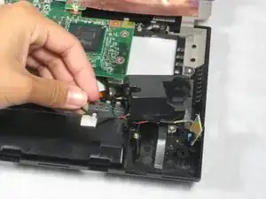
    • Pull the blue tab that holds the speaker chip and pull the chip out.

  26. WTcDVUpHmFyJN1gY
    WTcDVUpHmFyJN1gY
    XbGPvQD5YZ6WDiS1
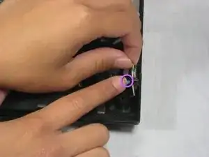
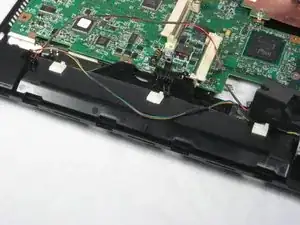
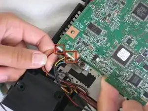
    • Remove the wires from the white tabs by lifting the black wire casing.

  27. XKVdYrMQDxOyJZLS
    XKVdYrMQDxOyJZLS
    MDdlbbjxIiQmVOsj
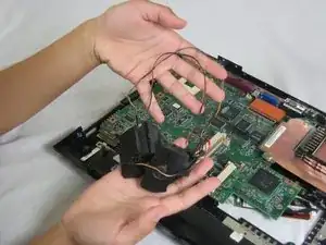
    • Lift the left speaker out.

    • Pull the blue tab that holds the speaker chip and pull the chip out.

  28. YuWKNMsCURrx5B2r
    YuWKNMsCURrx5B2r
    eFnxVDXn4uTxO5BT
    • Remove the speaker data and power cables by pulling them from the motherboard.

    • You have successfully removed the ThinkPad A30 speakers.

Abschluss

To reassemble your device, follow these instructions in reverse order.
Alan

Mitglied seit: 07/10/10

380 Reputation

0 Kommentare