Einleitung

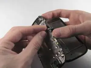
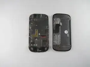
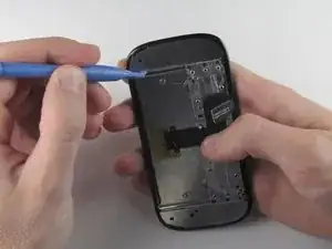
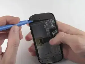
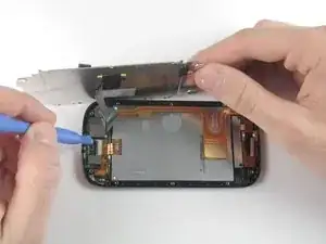
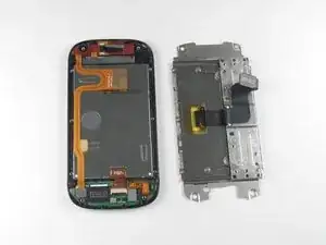
This is ONLY a prerequisite guide to remove the LCD shield plate in the Motorola Cliq.

  1. LjJMyCrFCl515tNF
    LjJMyCrFCl515tNF
    ILu2TIHlv6vvPIAR
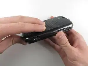
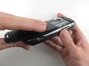
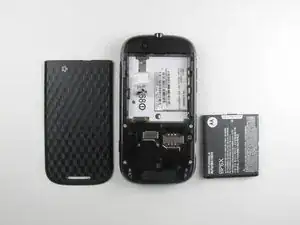
    • Turning over your phone, place two fingers on the back cover and apply pressure away from the camera to slide the back cover off.

  2. 6aDNNpQSxia4xACH
    6aDNNpQSxia4xACH
    YqVlqGZIChZLS1dN
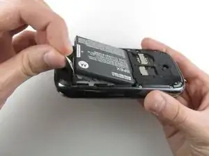
    • Pinch the battery pull tab located below the camera, pull it upwards, and remove the battery.

    • The pull tab may be tucked under the battery.

  3. nOGZB5iDBNLXEL6Z
    nOGZB5iDBNLXEL6Z
    DHW5bEdSSBOTr5iR
    YLki6oYBQsFJNMYr
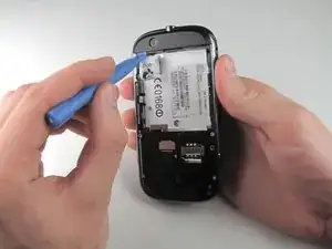
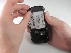
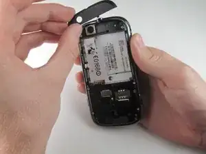
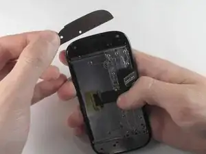
    • Wedge a plastic opening tool behind the panel covering the camera, pry it up, and remove it using your fingers.

    • The panel is held down by adhesive and may require you to wedge and pry the right side of the panel before it can be easily removed.

  4. j1ALLVZJq2piDXqP
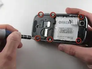
    • Remove the six 4.0 mm T4 Torx screws which line the edge of the back of the phone.

  5. dgXguKoRG3ZKgHbu
    dgXguKoRG3ZKgHbu
    XiFTVORAXUA1EN21
    rxUNvv3vVJ2ueh44
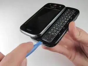
    • Turn the phone over and slide out the keyboard.

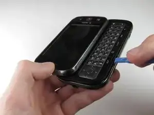
    • Wedge a plastic opening tool where the keyboard meets the back casing of the phone next to the headphone jack.

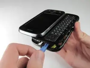
    • Carefully pry open the back casing along the keyboard's edge until at least two corners of the back casing are separated from the keyboard.

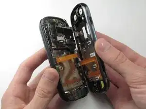
    • Do not fully separate the rear panel from the phone. A cable is connecting the two parts together.

  6. UMoJpSro6QcBEf6y
    • Carefully separate the back casing from the rest of the phone.

  7. pYCPEmnSo1PJ1gLw
    pYCPEmnSo1PJ1gLw
    X3B4dxcRpEG3SROn
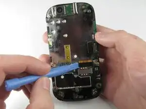
    • Gently pry ZIF connector upwards using the flat end of a spudger tool.

    • The ZIF connector is glued down. Be gentle! Ripping it off or breaking it will make your phone inoperable.

    • You may need adhesive to keep your power cable in place when reassembling your phone.

  8. qj1QyZRG5NqenaN4
    qj1QyZRG5NqenaN4
    2FUfBE4Yi13Kwpdm
    C5osXZ5MRKuww3DN
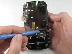
    • Press your thumb against the orange power cable and pull it down slowly to disconnect the power cable from the bottom of the keyboard.

    • The rear casing and the rest of the phone should now be completely separated.

  9. FF4YOyXG4QKFeHrA
    FF4YOyXG4QKFeHrA
    sZiZJRBYXuLVqkul
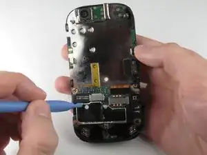
    • Wedge the plastic opening tool underneath the black display connector and pry it off its socket on the motherboard.

  10. X6EwSJA1DSciMBYG
    X6EwSJA1DSciMBYG
    XDd1tSAhiRDqHNFe
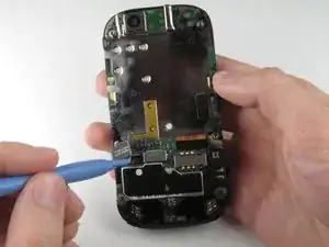
    • Pry the orange keyboard connector from its socket on the motherboard using the edge of the plastic opening tool.

  11. EiIFlAPo1oABqdY2
    EiIFlAPo1oABqdY2
    BVjjolYA3K3NVDkB
    pUrmUXISZCGxg1JG
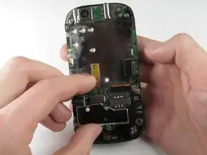
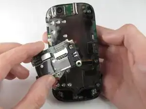
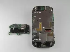
    • Carefully grab the sides of the motherboard with your fingers and remove it from the phone.

  12. ESNWC55DE2Htd2vQ
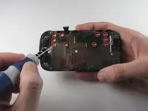
    • Remove the ten 3.0 mm T4 Torx screws near the black display cable.

  13. gmIpGpC64pZtF4Ys
    gmIpGpC64pZtF4Ys
    BFys4ICukVmRhLWq
    LMiO2TJy1VIYAnPn
    • Orient the phone so that the edge closest to the camera points towards you and slide out the keyboard.

    • Wedge the tip of a spudger between the keyboard and the display assembly below the camera.

    • With steady pressure, pry the keyboard away from the display assembly.

    • The keyboard and display assembly are glued together, so expect some resistance.

    • Do not completely separate the keyboard and display assembly because the display flex cable still connects them.

  14. vi4SZEhHAhO4fYgg
    vi4SZEhHAhO4fYgg
    CijlUwMFshWnX3mX
    26pTXiXROJEZngpF
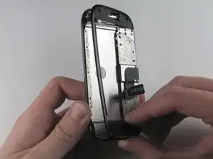
    • Grab the display flex cable and gently push it through the notch it is coming out of.

  15. 5CFBSpkhoiQQ4Bx3
    5CFBSpkhoiQQ4Bx3
    UNfKHgRVSahyRtQu
    BVOLeAxmjZNCQNlR
    • Wedge a plastic opening tool underneath one of the metal panels on the underside of the display assembly.

    • Pry upwards and remove the metal panel.

    • Repeat this step for the second metal panel located on the opposite side of the phone.

  16. EiWPrPsWPX6GpF3u
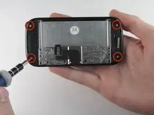
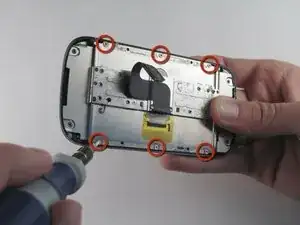
    • Remove the four 3.0 mm T4 Torx screws at the corners of the phone.

  17. QrsmLVSoopsH3GJE
    QrsmLVSoopsH3GJE
    yUBt5QSHcZbkHU5w
    IjDY6rTOKAMMGtai
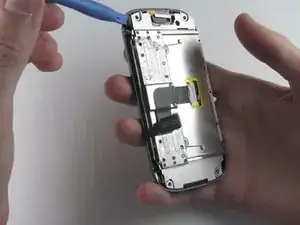
    • Wedge a plastic opening tool between the edge and the black pastic cover on the underside of the display assembly.

    • Run the plastic opening tool along the edges to separate the black plastic cover from the display assembly.

    • Remove the black plastic cover.

  18. 2Ace4lGduJkyaXfG
    • Remove the six 3.0 mm T4 Torx screws that align on the phone's sides.

  19. 4S45ROcWLUwNojZE
    4S45ROcWLUwNojZE
    oIL1jBXXlnRtvMAk
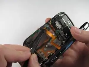
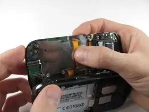
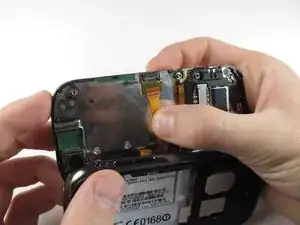
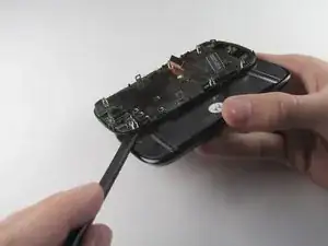
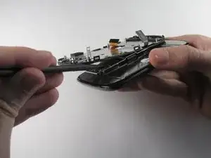
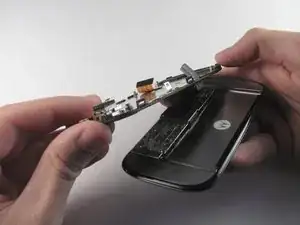
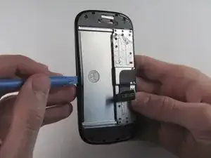
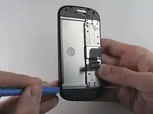
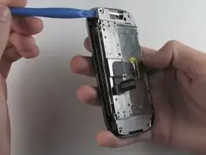
    • Insert a plastic opening tool between the LCD shield plate and a corner of the keyboard slider plate.

    • Pry apart the keyboard slider plate and LCD shield plate.

    • Do not completely separate them: the keyboard slider plate is still connected to the LCD shield plate via the display flex cable.

  20. GyZ1cTb1EU6fsCnL
    GyZ1cTb1EU6fsCnL
    cYH6C3Vr5sp4ugMK
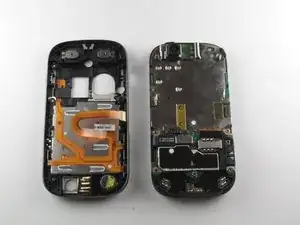
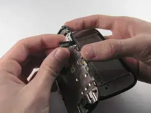
    • Pry the display flex cable from its connector on the LCD shield plate with a plastic opening tool.

    • Separate the display flex cable from the LCD cover plate.

Abschluss

To reassemble your device, follow these instructions in reverse order.
Tony Tran

Mitglied seit: 14/04/13

64 Reputation

0 Kommentare