Einleitung

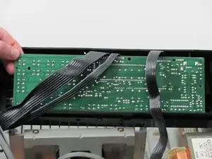
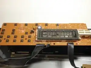
Separating the logic board from the face plate.

  1. ix6KwcUJI5MwbjfJ
    ix6KwcUJI5MwbjfJ
    xnd5otveFW1OyKKF
    YWhJEXW3qGgwkjVY
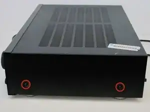
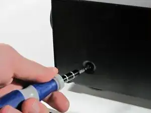
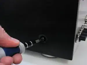
    • Remove the two screws on both sides of the receiver. Keep these and the rest of the screws in a safe place.

  2. ejY1sGgG1WIqWN2O
    ejY1sGgG1WIqWN2O
    2IGKvJuX3cEHRhe6
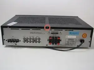
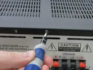
    • Remove the top screw on the back panel.

  3. QHhfuxrID3Id52LM
    QHhfuxrID3Id52LM
    oRF6swHN6NrHJnv2
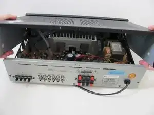
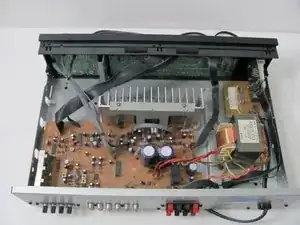
    • Slide off the case to expose the internal components of the receiver.

  4. BCIrXKYCdI111Xnh
    BCIrXKYCdI111Xnh
    KULhuCFK6b5JjeZF
    E4CPwK3dNGb1cAdc
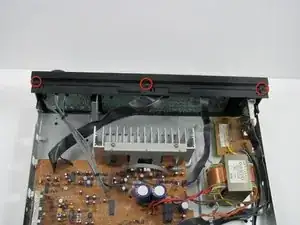
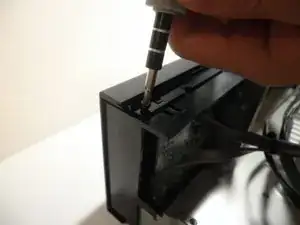
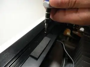
    • Unscrew the three screws on top of the face plate.

  5. gakTkBkwLpjTLjSl
    gakTkBkwLpjTLjSl
    BH1Yi4pjprgduwa4
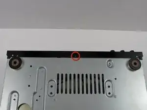
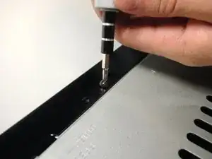
    • Unscrew the one screw on the bottom of the front panel.

  6. rqbmYGAhaEPPGrDf
    rqbmYGAhaEPPGrDf
    AkdXRM3WeMmHPQw2
    VJw33aqwIsQfgk4D
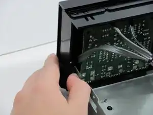
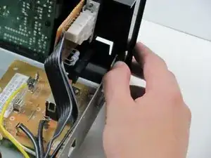
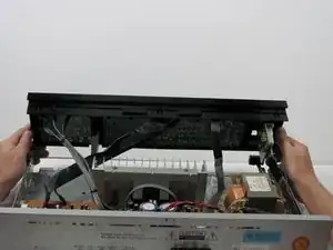
    • Simultaneously push down on the head of the snap on each end of the device with your thumbs and push to seperate the face plate. This may take some force.

  7. NAKcRALXFH1aexSc
    NAKcRALXFH1aexSc
    XLRenXkFSqwblRt1
    kpdYEITJLlEOZVhm
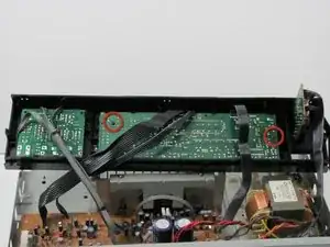
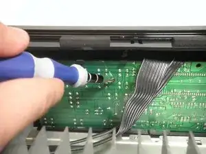
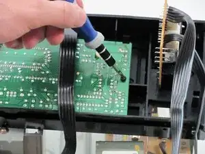
    • On the inside middle of the face plate you will see two screws in the logic board. Unscrew these two screws.

  8. xquhRtUa3PMolwGT
    xquhRtUa3PMolwGT
    MUBUlIescJNVVFHE
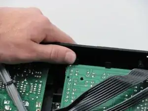
    • You will see the same snaps along the top of the logic board. Press the heads of the snaps down and pull the logic board out and up.

Abschluss

To reassemble your device, follow these instructions in reverse order.
Ryan

Mitglied seit: 13/04/10

108 Reputation

0 Kommentare