Einleitung

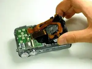
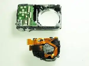
The lens can be safely removed in only seven simple steps.

  1. CBWJSCZkKmRc6yfV
    CBWJSCZkKmRc6yfV
    VNQGWKNVZQvFn4QW
    vNYKEJEnoUlXiiR1
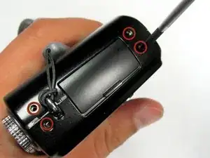
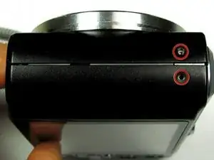
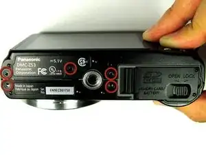
    • Remove the following eleven screws securing the covers to the ZS3

    • Eleven 3 mm Phillips screws

    • Using too much pressure when removing the screws may strip the screws and complicate screw removal at a later time.

    On some versions of this model, removing the back cover will suffice for this repair. The back cover is secured by only six screws.

    Alex Levine -

  2. xjFAS1DqKCFdgoXC
    xjFAS1DqKCFdgoXC
    YjGiN3sWfvgUcgAB
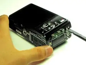
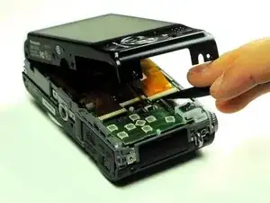
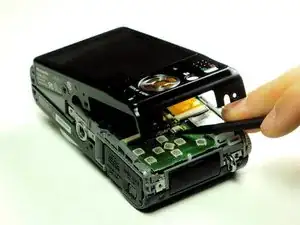
    • Use the flat end of a spudger to pry apart the back cover from the rest of the unit as shown.

    • Be sure to carefully and slowly lift the back cover. Forcefully lifting the back cover and fully separating it at this point may ruin internal connections.

  3. qoG2JfDBMJ6yHq6c
    qoG2JfDBMJ6yHq6c
    tQDRZU3XCBIqixD4
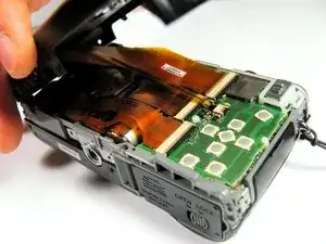
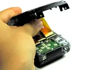
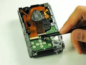
    • Using your fingernail or a spudger, flip up the ZIF locking flap on the two LCD ribbon cable sockets that connect the back cover to the rest of the unit.

    • Be sure you are opening the locking tab, not pulling against the socket mounted to the board.

  4. SN6UjZKSqv3plYMe
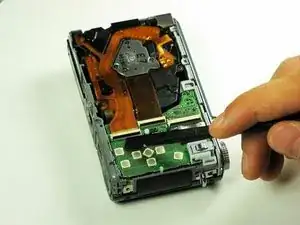
    • Remove the two LCD board ribbon cables out of their sockets.

    There are two ribbon cables: a wide one for the lcd display itself, and a thin one for the backlight. When reassembling, it is easy to reverse the polarity on the backlight cable, in which case the backlight will not work. Make a note of the polarity as you disassemble.

    Alex Levine -

    when I pried the small band's socket, the socket came off the board. What do I do now ? can I resolder it and where to ????

    Karen Kornbau -

  5. HqaCbE3SBp3YHjwH
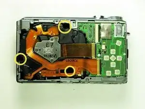
    • Remove the three black screws that surround the lens.

    • 3mm Phillips screws

  6. 45ZBEUTsY2kY2lgq
    45ZBEUTsY2kY2lgq
    nKETwYSAENhBYIFR
    uLaprSAOyyLpsZPI
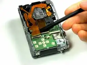
    • Using a spudger, flip up the locking flaps on the two LCD ribbon cable sockets that connect the back cover to the rest of the unit.

    • Disconnect the LCD ribbons gently using the spudger.

  7. e4F3RdVdNiSRasGu
    e4F3RdVdNiSRasGu
    PGkDFjYet5pbyWDS
    RQhFLldVGlUKQJVi
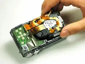
    • Using your fingers or a spudger, gently remove the lens mechanism from the rest of the camera.

    • Unlock lens mechanism located on the bottom of the device using your fingers.

    • Be sure to not use excessive force to avoid damaging any parts.

Abschluss

To reassemble your device, follow these instructions in reverse order.
Kellen Ericson

Mitglied seit: 18/04/13

18 Reputation

0 Kommentare