Einleitung
The Deebot 920 is similar in construction to the Deebot 950, and you may be able to use portions of this guide to assist in disassembling that vacuum as well.
With this guide, you should be able to access and replace a variety of components, including the beater bar, battery, drop sensors, water pump, wheels and wheel motors, side brush motors, and the beater bar motor.
While the disassembly itself is only of Moderate difficulty, due to the hassles in reassembly and care required, it has been marked as Difficult. Allocate an additional 1-2 hours for reassembly.
-
-
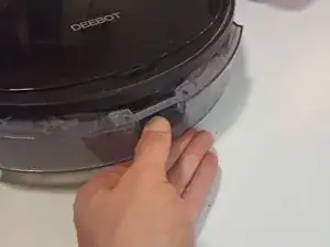
Use the thumb tab to remove the water resivoir.
-
Lift the lid and remove the dust bin and cleaning brush.
-
-
-
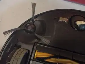
Turn the unit over, then locate and remove the side brushes by pulling them straight up.
-
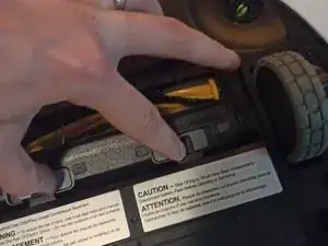
Slide the tabs to remove the beater bar retainer, then slide out the beater bar from its square drive.
-
-
-
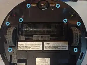
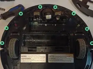
Remove the 8 black 7mm screws from the skid plate.
-
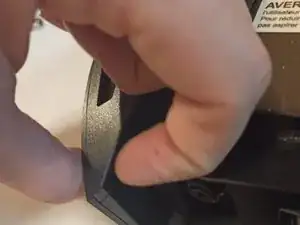
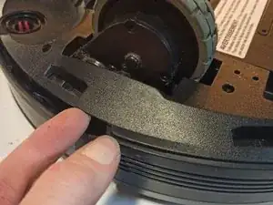
Lift up the skid plate from one of the corners by the water reservoir and remove.
-
If you have difficulty, you can also try to pry up the plate from the edge by the front bumper.
-
-
-
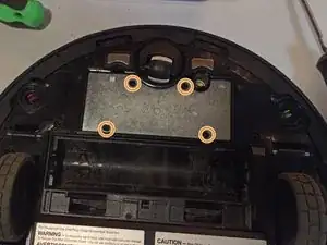
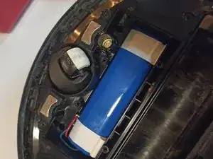
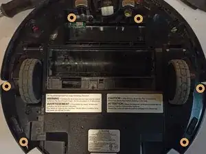
Remove the 4 black 10mm screws from the weight.
-
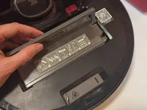
Lift the white tabs on the battery to remove it, and unplug it from the motherboard.
-
-
-
Remove the 8 black screws from the front bumper stiffener using a #00 or #0 Phillips screwdriver.
-
Remove 6 black 10mm screws retaining the top cover.
-
-
-
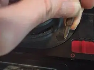
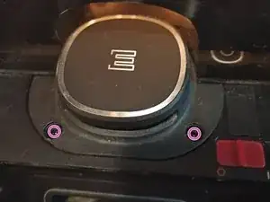
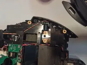
Flip the unit back over. Use a small flathead screwdriver or spudger to remove the rubber covers near the laser sensor.
-
Remove the two washer head screws.
-
-
-
There are 6 clips holding the top cover to the base.
-
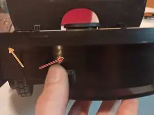
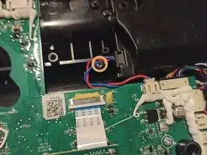
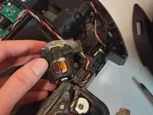
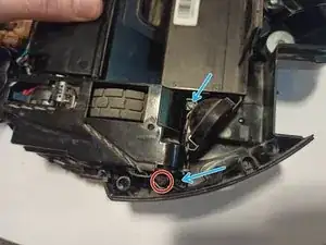
Press in at the red arrow, by the water reservoir retention hook, to detach an internal retention clip.
-
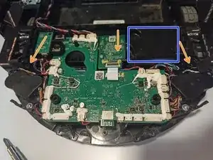
Pry up on the top cover at the orange arrow to begin unclipping the top of the unit.
-
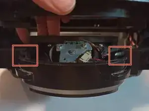
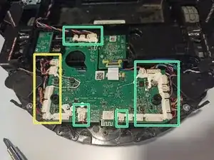
Two additional clips are at the yellow arrow on either side of the unit. Pressing in at these locations aids in their removal.
-
-
-
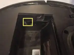
The yellow rectangle indicates the location of the side clips in the dust bin area.
-
The final two clips are at the front of the case and should free themselves with a little lifting force and wiggling.
-
-
-
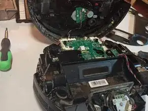
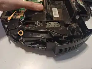
Remove the two silver washer head screws holding down the vacuum assembly with a #1 Phillips driver.
-
Unplug the motor from the motherboard and remove the entire assembly.
-
-
-
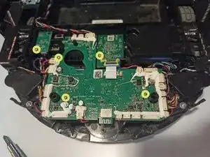
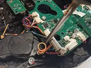
Remove the 5 silver 7mm screws retaining the motherboard and daughter boards.
-
Fold down the center daughter board and remove the hidden silver 10mm screw. This screw holds in the beater bar housing and can be skipped for other repairs.
-
Remove all of the cables connecting the motherboard to the rest of the unit.
-
Depending on your repair, you may not need to remove all or any connectors to access the necessary screws.
-
-
-
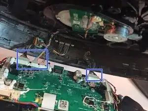
Remove the two silver 7mm screws from the side trim panel, and the two silver 7mm screws from the water pump retention clip.
-
Lift out the water pump, being aware of the water lines coming from the side and running underneath it, and place it into the dust bin area (if not replacing).
-
If replacing the water pump, remove the two water hoses from their barb connectors, unplug the motor from the motherboard, and remove.
-
-
-
Remove the two silver 10mm screws holding each side brush motor.
-
Unplug each motor from the motherboard, if necessary, and remove.
-
-
-
Remove the 4 silver 10mm screws on each wheel well.
-
Do not errantly remove or adjust the black spring retention screw.
-
-
-
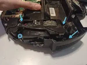
Almost all components, save the suction motor, must be loosened or removed to extract the housing.
-
The beater bar housing is held in by the hidden screw beneath the center daughterboard, as well as one screw from each of the wheel wells.
-
After removing surrounding components, lift up on the motor housing (outlined in blue) and allow it to hinge back towards the dust bin area, pivoting on the 135-degree area.
-
Once the housing for the two internal hinges for the beater bar are free, slide the beater bar housing up and out of the case towards the front.
-
-
-
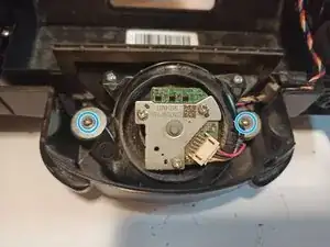
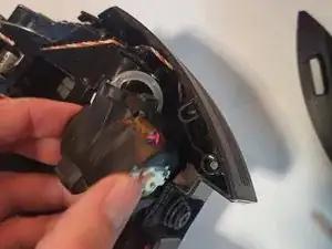
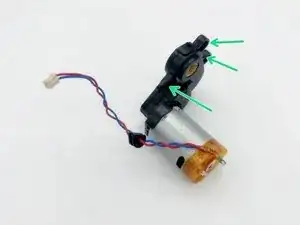
Remove the three screws on the side of the beater housing which hold down the motor and its gear case.
-
Push the rubber grommet through the housing towards the motor, and slide the rest of the cable into the housing to free the motor.
-


To reassemble your device, follow the separate 'reassembly' guide.