Einleitung
This guide showcases the care and precision required to reassemble the Deebot OZMO 920. This unit is similar to the Deebot 950 and some sections may be useful to owners of that vacuum.
The screws on this unit are tapped into plastic, and therefore excessive force is not required in tightening them, nor is thread locking compound.
-
-
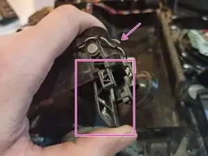
If removed, slide the wires for the beater bar motor through their access hole, and force the new grommet through the hole as well. Place the grommet into it's holder. Assembled photo for reference.
-
-
-
Slide the assembled beater bar housing into the unit from the front (bumper) with the internal hinges (the pointy bits) pointing forward. Ensure that the floating beater bar holder is underneath the housing and moves freely.
-
Ensure also that the side tabs on the diagonal portion of the housing are outside of the sides of the dust bin area.
-
Ensure that the housing for the rubber dust funnel is properly seated in the beater bar housing and to the rest of the unit case.
-
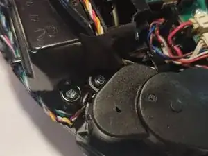
Check for wires that may be trapped underneath the internal hinges. Add one silver 10mm screw to the center of the housing to retain it.
-
-
-
Each wheel well has a traction spring which pushes down on a finger in the housing, keeping the wheels firmly on the ground.
-
The finger rides along a bushing on the side of the wheel.
-
The spring-loaded fingers must be pushed up into the housing all the way, and then the wheels inserted underneath them so that the spring rests on the bushing.
-
The leeway for keeping the wheel in the appropriate location while all of the screws are removed from the wheel well is very small, so compression must be applied constantly between the wheel and wheel well to prevent the spring from dislodging.
-
The wheel should be fighting you constantly. If it is not, restart by setting the spring back onto the bushing.
-
-
-
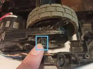
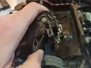
When fully inserted and screwed down correctly, the reed switch (which indicates to the system that the wheel is off the floor) should be fully compressed, and the plastic finger which depresses it should be at or near the top of the silver portion of that switch.
-
An incorrectly installed wheel may not depress the switch completely, and may not reach the top of the silver area. The usual culprit is a pinched wire.
-
-
-
Depress the spring to the left wheel well housing and push the wheel inside of it, keeping tension on the spring. Ensure that the spring rests on the wheel bushing.
-
Move the sensor wires running along the outside of the case up and over the screw peg temporarily.
-
Ensure that the rubber grommet which routes power to the wheel motors is positioned in its half-moon seat. This grommet is located towards the front center of the unit.
-
Seat the wheel well into position, and, while still applying pressure to the wheel, install two silver 10mm screws into opposing corners of the housing.
-
Ensure that no wires have become trapped.
-
Install the final two silver 10mm screws.
-
-
-
Repeat the process on the other side of the vacuum.
-
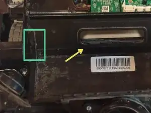
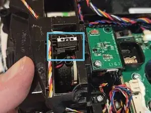
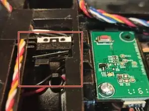
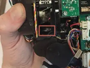
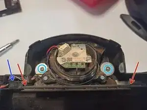
Ensure that no wires have become trapped under the front of the housing. The area highlighted in red shows that the white/green/blue wire is pinched.
-
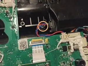
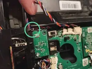
The next image shows that the pinch has been resolved, and a beautifully aligned reed switch.
-
-
-
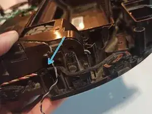
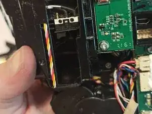
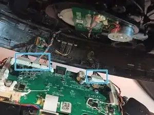
While installing the housing into the unit, ensure that each of the three wire bundles coming out of the top of the motherboard by the power switch are placed underneath this plastic tab. This tap keeps them from being pinched when the top cover is replaced.
-
Replace the sensor wires which were temporarily placed outside of the screw pegs.
-
-
-
Ensure that the speaker on the left side is correctly placed in its half-moon seat.
-
If removed, connect the pump to the water lines.
-
Install the pump clip with two silver 7mm screws.
-
-
-
Use two washer head screws to install the suction motor with a #1 Phillips bit.
-
Ensure that the rubber gasket for the motor screen is correctly seated into the bottom housing.
-
Ensure that the dust bin sensor switch is correctly seated.
-
-
-
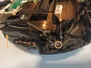
Clean the left side piece, which acts as the suction output. It may have built up dust or debris.
-
Install each side piece with two silver 7mm screws.
-
-
-
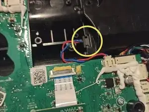
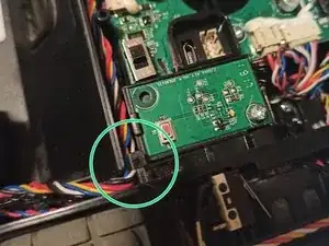
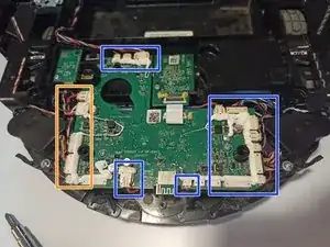
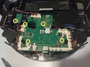
Reconnect all wires to the motherboard, ensuring that any connectors underneath the board on the left side of this image (marked in orange) are also connected.
-
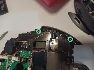
Install the motherboard and daughter boards with five silver 7mm screws.
-
-
-
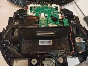
Check over the inside of the unit to ensure that no wires are sticking out of place. Wires along the sides of the unit should be properly routed into their own retention clips to avert any risk of damage.
-
Confirm that all of the motherboard connectors are fully seated. Each connector should be of the appropriate length to reach its intended plug, and due to the size and location of each connector, there is little chance of ambiguity in connecting these.
-
-
-
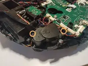
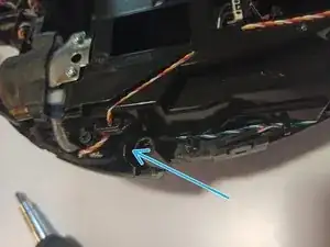
Attach the four motor and sensor wires coming from the unit lid to the motherboard.
-
Fold the top down over the vacuum and snap it into place.
-
-
-
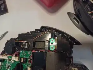
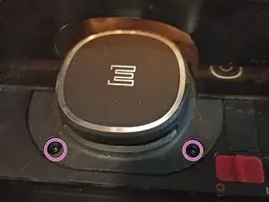
Install the two black washer-head screws near the power switch, and replace the rubber covers.
-
-
-
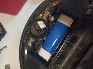
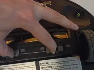
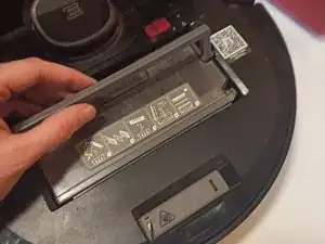
Plug in the battery to the motherboard, and place it down into its recess. Ensure that at least one of the white tabs is accessible for future maintenance.
-
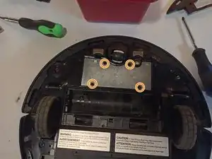
Install the weight over the battery and secure it with four black 10mm screws.
-
-
-
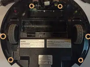
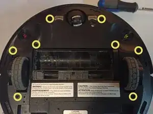
Apply the bottom of the bumper to the unit. Install the eight small black screws with a #0 Phillips bit.
-
-
-
Install the beater bar into its square drive hole, and install the cover plate. Install the color-coded side brushes.
-
Turn the unit right side up.
-
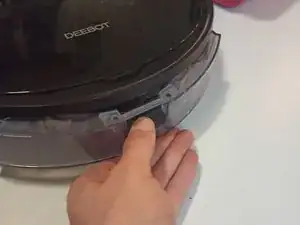
Install the dust bin and replace the cleaning brush, and install the water reservoir.
-


Switch the device back on, and allow it to boot. Place it in front of its docking station, then press and hold the power button for three seconds to send the unit back to its docking station.