Einleitung
The charging port of your device can fail due to hard impact or general fatigue from repeated use. After purchasing a new charging port and following this guide, your device will be ready to work for you again.
Werkzeuge
Ersatzteile
-
-
Power down your device.
-
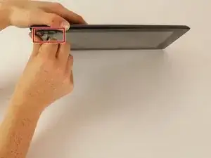
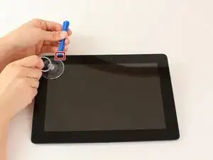
Place the small suction cup on a corner of the screen and lightly pull up to expose a seam between the screen and case.
-
-
-
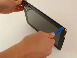
Insert the plastic opening tool into the seam near the corner of the device.
-
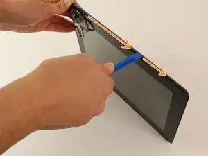
Slowly slide the tool around the perimeter of the device, gradually prying up the screen.
-
-
-
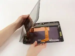
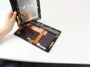
When the screen is free of all spring clips and adhesive, slowly open the device like a clam shell with the hinge being the left hand side of the device.
-
Safely place the device back on the table by laying the screen face down.
-
-
-
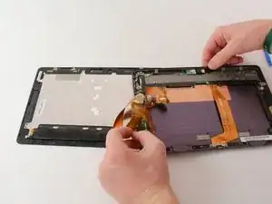
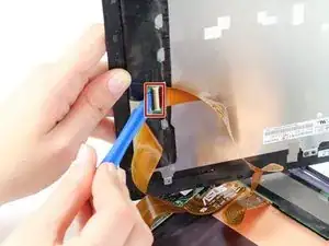
Disconnect the ribbon cable by placing a plastic opening tool under the black plastic tab that is on the opposite side of the port as the ribbon cable.
-
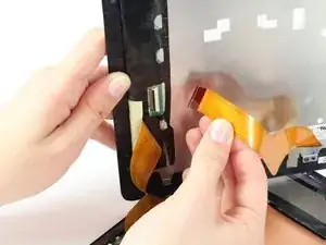
Pry upward until the black tab moves 90 degrees, and gently pull the ribbon cable out of the port.
-
-
-
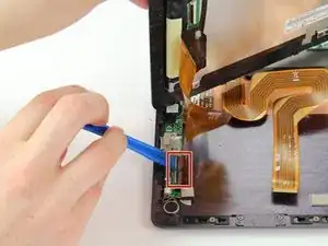
Place a plastic opening tool under the white plastic tab on one of the ribbon cable ports.
-
Pry upward until the black tab moves 90 degrees, and gently pull the ribbon cable out of the port.
-
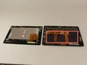
Repeat the previous process to remove the other ribbon cable.
-
-
-
Remove the battery (secured by six screws and a white wire connector) by following the removal portion of this battery replacement guide.
-
-
-
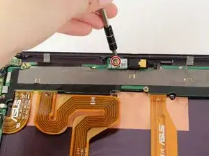
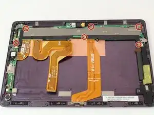
With a Phillips #00 screwdriver, remove the one 3.8 mm screw in the LED chip. The LED chip is a small green chip (about 1 square centimeter) located at the top center of the device.
-
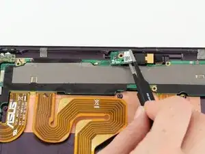
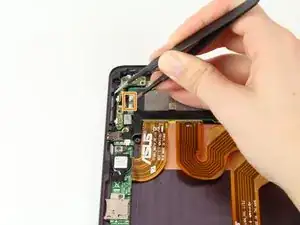
Gently remove the chip with a pair of precision tweezers by grabbing the chip from one side, being careful not to pinch on a black piece of hardware on the chip.
-
-
-
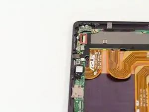
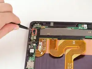
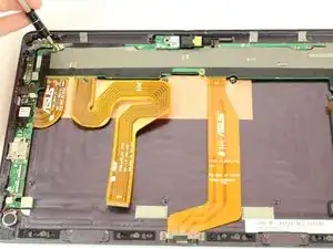
With precision tweezers, pull back the strip of black tape covering the connection between the button key switch and the motherboard.
-
Disconnect the wires by using precision tweezers to gently pushing the black plug out of the white receptacle.
-
-
-
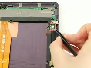
Disconnect the speaker assembly from the motherboard by using precision tweezers to unplug the white plug from its tan receptacle.
-
-
-
Disengage the right side of the motherboard by gently sliding the audio jack out of the device case.
-
With one hand, gently pull the wall of the device outward. With your other hand, pull the motherboard and audio jack to the inside.
-
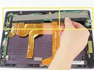
Remove the motherboard by lifting the right side, and sliding the motherboard slightly to the right to free the left edge.
-
-
-
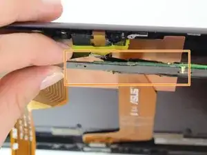
Disengage the camera connections and yellow tape by gently pulling up on the motherboard while holding the yellow tape and camera connections down.
-
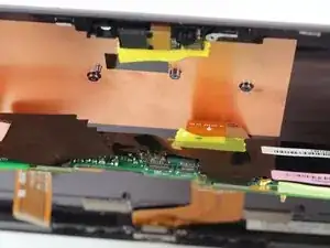
Fold the motherboard toward you 180 degrees and set it down in the middle of the case.
-
-
-
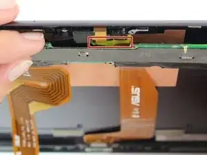
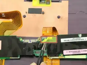
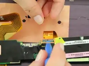
With precision tweezers, peel back the yellow tape in the center of the motherboard to expose the ribbon cable to the charging port.
-
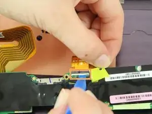
Lift the tan tab on the back of the ribbon cable port upward 90 degrees with a narrow plastic opening tool.
-
Pull the ribbon cable out of the port, freeing it from the motherboard.
-
-
-
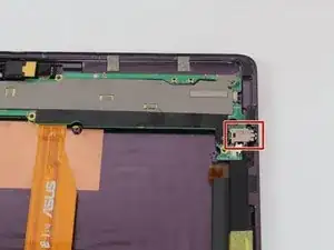
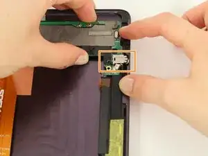
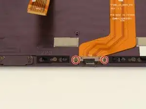
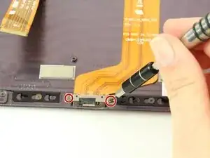
With a Philips #00 screwdriver, remove the two 2.5mm screws on the charging receptacle.
-
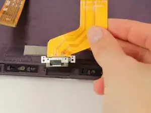
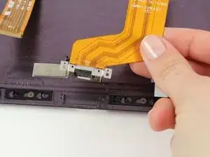
Remove the charging receptacle and ribbon cable.
-
To reassemble your device, follow these instructions in reverse order.
Ein Kommentar
On my TF201 it says always “not charging” when i plug the charger. But the Amp-meter shows 900mA and the charging process is fine. What's the issue?
K. Bez -
