Einleitung

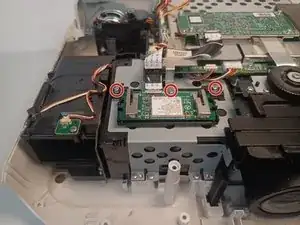
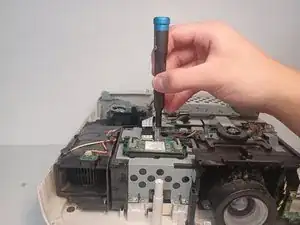
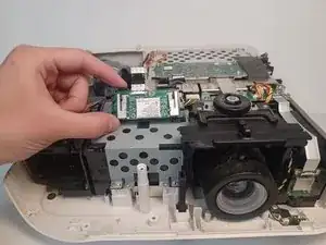
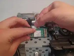
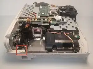
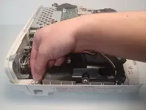
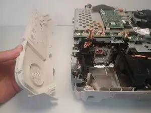
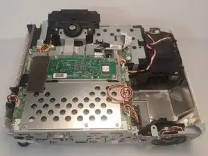
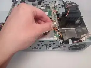
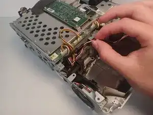
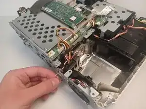
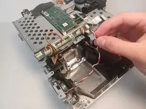
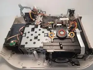
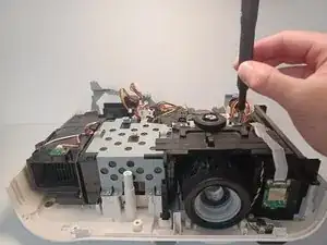
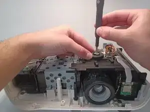
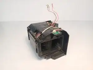
Fans are a mechanical component subject to wear and tear. Mechanical components are often the first to fail. In the event the exhaust fan within the projector begins to emit unpleasant noises, the exhaust fan may need to be replaced.

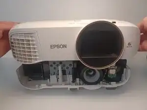
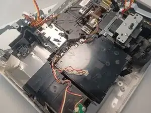
It is located inside the projector on the same row as the projector lens, all the way to the left, next to the power supply.

  1. evmtVfdxTXigVVcH
    evmtVfdxTXigVVcH
    ZNwM2AT1oRrBZqDl
    XtQbBDmvTq4D1poX
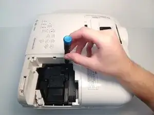
    • Disconnect and cool the device to room temperature. Failure to do so may result in electric shock or minor burns.

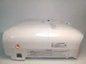
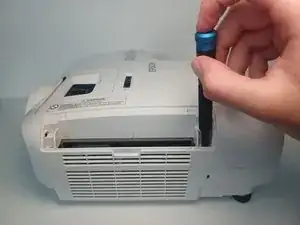
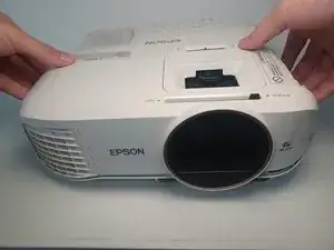
    • Orient the Epson Home Cinema 2150 so that the large indented panel faces your direction.

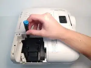
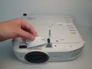
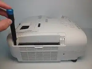
    • Unscrew the single 6mm Phillips#2 holding screw from the access panel.

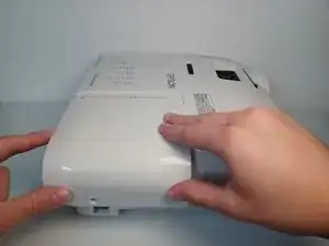
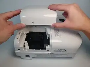
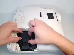
    • Slide the panel horizontally, then lift up to remove the access panel.

    Great job identifying your tools under the “Tools” section. Make sure it’s correct for your intro too.

    Naomi Zaldana -

  2. bae2Cx3DQe5GPLOT
    bae2Cx3DQe5GPLOT
    qnBPC1spDMqmYcNv
    qfTcM4SSXI1LGUGd
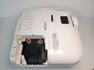
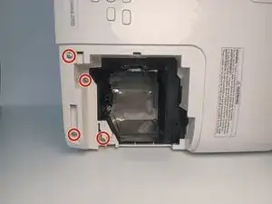
    • Loosen and remove the two screws holding the lamp.

    • Remove two 9 mm Phillips #2 screws.

  3. SmYqsTVLBxnYObaY
    SmYqsTVLBxnYObaY
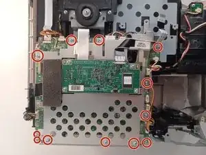
    hPBIMmyAccOaU3Tr
    HYoXVjBSMyBuy4Pm
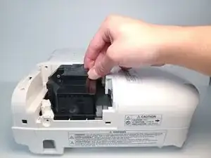
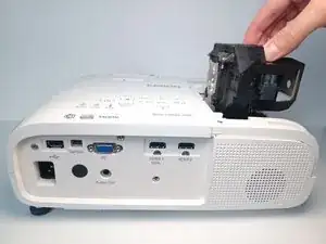
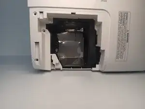
    • Using four fingers, pull upwards on the lamp's plastic casing.

    • You may feel some resistance when pulling the lamp.

    We noticed these steps are exactly like the first 3-4 steps of your other guides. We would recommend you to make this a prerequisite guide for those 3-4 steps (mostly unscrewing to open the device up) and then reference them before starting the other replacement guides.

    Naomi Zaldana -

  4. ZxCtHSy4q6fGvTCi
    ZxCtHSy4q6fGvTCi
    gRiYh5O5lwB3mKFp
    JyDbYjNMGoZWkUom
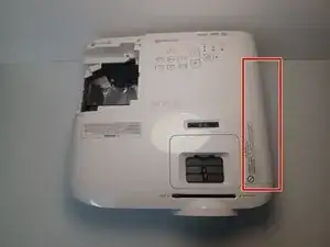
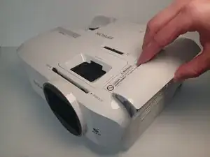
    • Remove the air filter cover. Grip the piece with two fingers above and below at the center.

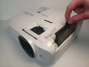
    • Grab the air filter from the protruding tab and pull the filter out.

  5. KRbPWWNOTDgmKxUY
    KRbPWWNOTDgmKxUY
    LwSAiPrl1OKmVwnc
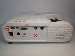
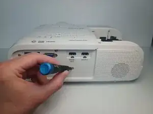
    • From the back of the projector remove three 6 mm Phillips #1 screws.

  6. HNChvVMk4s3cSROs
    HNChvVMk4s3cSROs
    Gf6XuhYfhrZFjupJ
    ukxKplZfIxNGTaXX
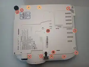
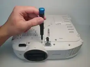
    • From the device's underside, remove eleven 9.5 mm Phillips #1 screws.

    • Remove two 6 mm Phillips #1 screws.

    • Pull off remaining plastic molding.

  7. EbwHKYWSbbiOvjSe
    EbwHKYWSbbiOvjSe
    HAC5fcR1HdLOrGFb
    • From the lamp access slot, remove four 9.5 mm Philips #1 screws

    4 screws to be removed but only 3 are marked. Because it may not be visible, simply mark where it is hiding for the user to know where to look.

    Naomi Zaldana -

  8. MTNujGEBc4UEeoNL
    MTNujGEBc4UEeoNL
    IveRfMUKBDvhmG43
    gAhxAa5cA4YyCl1Q
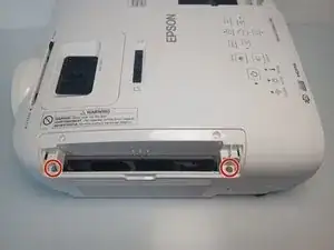
    • From the filter slot, unscrew two 9.5 mm #1 screws.

  9. SenfiE1yAjYTpYnV
    SenfiE1yAjYTpYnV
    IEWkuCFoLmLK6lkj
    wiiPShGKbFLTIbXD
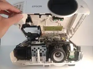
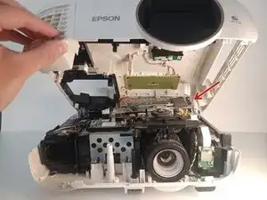
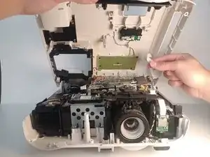
    • Partially lift the top portion of the device housing.

    • Lifting too far or too hard may damage any cables between the housing and the motherboard.

  10. VhZVfrSFixyAUo6d
    VhZVfrSFixyAUo6d
    gjvq1j4ffCaAZdZF
    WVVlPDESB5hZKRiL
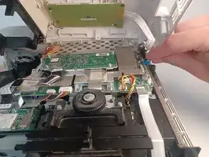
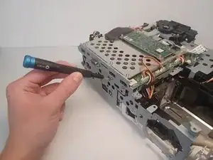
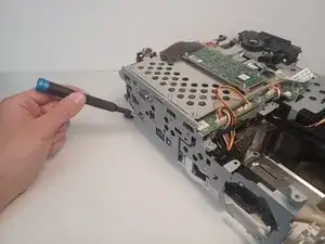
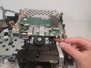
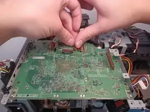
    • Disconnect the ribbon cable from the motherboard.

    • Ribbon cables are delicate. To avoid unnecessary stress to the cable, pull on the cable with the flat surface of two fingers.

  11. qh1GGVPwcOveIlJb
    qh1GGVPwcOveIlJb
    5f6GbRh31taZUIxm
    HJgWboOdyxuuS4Wj
    • Remove three 5 mm Phillips #1 screws.

  12. NPllsZlUhsTvjUfD
    NPllsZlUhsTvjUfD
    FAHYOdjYJQxUFvLI
    • Press on the metal connector and firmly pull on the remaining ribbon cable.

  13. efdSxcHGbNxmpvyQ
    efdSxcHGbNxmpvyQ
    2JRU5idctyfUSKtb
    qXotB2wTEkPCEd1C
    • Pull the clips on the case with two fingers on opposite ends and remove the case.

  14. FSqGUuRm5eNvHJUU
    FSqGUuRm5eNvHJUU
    JoanhSvXVFDDKWWn
    cWRP1ghOqdiCAPHA
    • Pull up on the rear panel retaining clip.

    • Pull the rear panel away from the device to remove.

  15. FytWDgFWvpJVLIMe
    FytWDgFWvpJVLIMe
    6f3gOQpiATCswcHR
    • Disconnect the speaker wire from the motherboard.

    • Pull up at the end of the wire when removing the connector.

  16. D3mXGZdsKtZxUPZM
    D3mXGZdsKtZxUPZM
    3cHWXH4bPBXfFiLf
    sUDdlkYudABXTyhn
    • Unwind the speaker wire through the metal chassis.

  17. krD1LrPtDhHnLkmi
    krD1LrPtDhHnLkmi
    tcKUVIfKAYFXLAGG
    hiNuHKFCEE5vmnF2
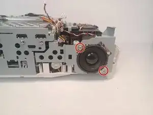
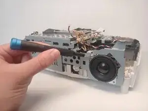
    • Remove two 6mm Phillips #1 screws.

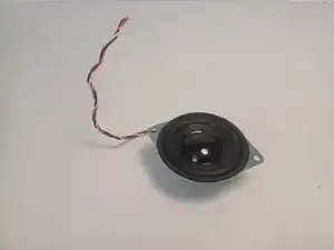
    • The speaker will fall out once screws are removed.

  18. INbnJbXG4FXQAh6u
    INbnJbXG4FXQAh6u
    OGkInyfDwKofmnBv
    JGhkN5KKJLW4LPbX
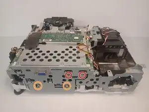
    • Remove two 6 mm Phillips #1 screws.

    • Remove two 5 mm Phillips #1 screws.

  19. 5TtbHgyY24Bn3ptJ
    5TtbHgyY24Bn3ptJ
    2oQrcDgnw4u4MsT2
    Q4TueNFOFTMlPCf1
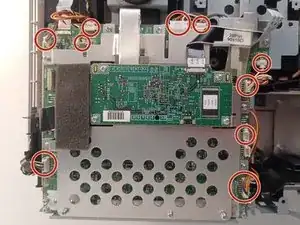
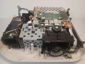
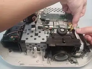
    • Disconnect a total of 10 motherboard connections.

    • Disconnect wires individually to avoid potential damage to the motherboard or the wires.

  20. mLBLf2HwOqBbFAZa
    mLBLf2HwOqBbFAZa
    ZXvqQVcnaUZqSSel
    RMj2oTBxFEljftaH
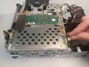
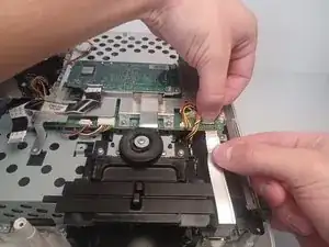
    • Press on the metal connector and firmly pull to remove the remaining ribbon cable.

    • Ribbon cables are delicate. To avoid unnecessary stress to the cable, pull on the cable with the flat surface of two fingers.

  21. h2soZANFCcF6jEgb
    h2soZANFCcF6jEgb
    NlvA53oKKUj5xUkJ
    aCZYFKAG1c1B4sQI
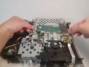
    • Remove twelve 5 mm Phillips #1 screws.

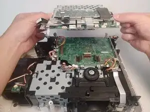
    • Using both hands, carefully lift the first half of the motherboard.

  22. AsBUNtsKQUEUH3Ij
    AsBUNtsKQUEUH3Ij
    Cm5TppoUKD2daxTm
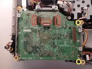
    • Disconnect the three brown ribbon connectors from the board.

    • Ribbon cables are delicate. To avoid unnecessary stress to the cable, pull on the cable with the flat surface of a finger.

    • Remove four 5 mm Phillips #1 screws.

    • Remove two 3 mm Phillips #1 screws.

    • Pull upwards on the motherboard to remove it from the projector.

    Wonderful markup examples!

    A humble recommendation would be to indent a note/reminder if it is specific to a particular bullet/step as seen with this one.

    Naomi Zaldana -

  23. xC3BXYaXXXRFlPe2
    xC3BXYaXXXRFlPe2
    PFmJUZRjFm5SlEnh
    Ymr6cj22qaSZKfkU
    • Remove the 7.5 mm Phillips #1 screw.

    • Remove two 6 mm Phillips #1 screws.

    • Set the black plastic lens sliders to the side.

  24. BG1lSuZPw6wfu5Zq
    BG1lSuZPw6wfu5Zq
    2mSXvCiYRVFeLAmg
    i2ZaHIfxQ1bK5aIW
    • Remove five 9.5 mm Phillips #1 screws.

    • Remove one 6.0 mm Phillips #2 screw.

    • This screw is located to the right of the rear 9.5 mm screw.

    • Remove the metal bracket by pulling upwards on its sides.

  25. cn3aOmaMLKYLYqak
    cn3aOmaMLKYLYqak
    5wEJfNDlvp6dVk1B
    seHq5mtvKQXwLMXW
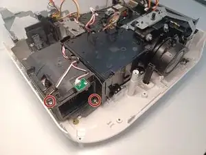
    • Remove the 9.5 mm Phillips #1 screw located behind the power supply.

    • Unwind the fan cable from the power supply for better access to the screw.

    • Remove the 10 mm Phillips #1 screw.

  26. iFDMDonJTeJxWQhd
    iFDMDonJTeJxWQhd
    4BeqSTOyPoVDFlJS
    aPlNqr6ey2umXrXL
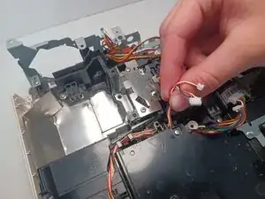
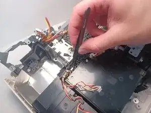
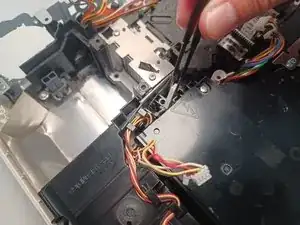
    • Move the fan cable to the side for clear access to the sensor below it.

    • Using pliers, pull upwards on the white sensor to remove it from the fan assembly.

  27. 1CixpHd4MFcEVnhY
    1CixpHd4MFcEVnhY
    PxWjTO2nSWOhWiPT
    ylWmRtS41DSYXILq
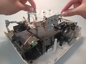
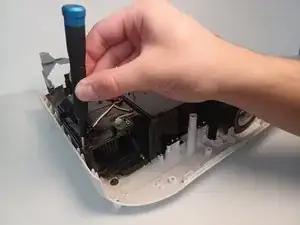
    • Remove two 9.5mm Phillips #1 screws.

  28. 6NOo5sJOTvJWQLNR
    6NOo5sJOTvJWQLNR
    xay1o2iOyMrgFWZF
    B6Mb6bmEprYQLLZC
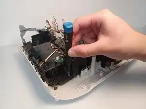
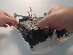
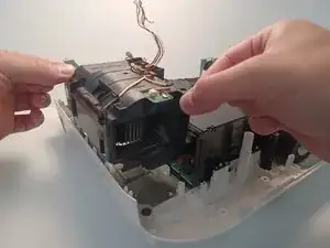
    • Carefully lift upwards on the fan assembly to remove the fan from the projector.

Abschluss

To reassemble your device, follow these instructions in reverse order.
Luis Garcia

Mitglied seit: 26/09/22

577 Reputation

0 Kommentare