Einleitung
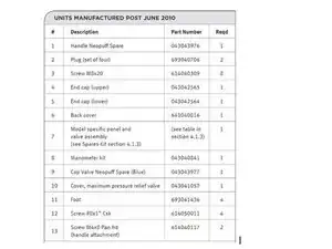
NOTE: The valves are an integral part of the valve, panel and manifold assembly and are not able to be serviced. Please specify the model number from the parts list (section 4.1.2) when ordering a replacement valve assembly.
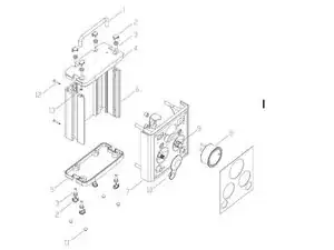
Please reference the parts list below for the disassembly diagram.
Please refer to page 7 of the device’s Technical Manual for source information.
Werkzeuge
-
-
Carry out the valve system performance test described above. It is recommended to record the lot number of the new valve assembly onto the Set-up and Maintenance Checklist.
-
Abschluss
To reassemble your device, follow these instructions in reverse order.

