Einleitung
Werkzeuge
-
-
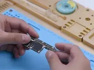
The phone had no service after being dropped and couldn’t be activated after a system upgrade. Firstly, inspect the appearance of the motherboard. The motherboard is not deformed or water damaged.
-
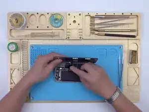
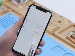
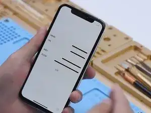
Then we install the motherboard on the phone to test. Connect the display and battery. Insert the SIM card. The phone can be turned on. However, the ICCID is not showing, which indicates that the SIM card is not read.
-
-
-
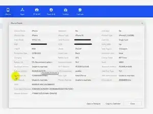
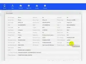
Connect the phone to the computer. Open 3uTools and view device details. 3uTools is unable to read data of the baseband version and Wi-Fi module.
-
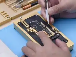
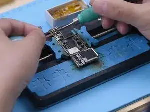
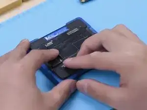
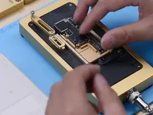
Because the phone had no service after being dropped. It can be preliminarily judged that the pseudo-soldering of the middle layer may cause the trouble. Next, we need to separate the motherboard. Put the motherboard on the Heating Platform and peel off the foam.
-
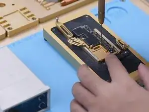
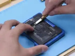
To make it easier to remove the logic board after separation, drive a screw on the logic board. Cut through the tape with a sculpture knife.
-
-
-
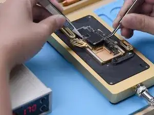
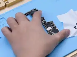
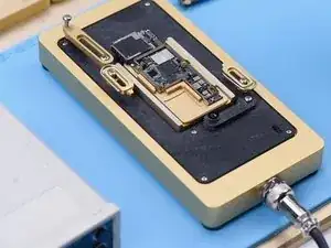
Set the temperature of the Heating Platform to 180℃ to heat the motherboard. When the temperature reaches 180℃, press the signal board with a pair of tweezers. Clamp the screw to remove the logic board with another pair of tweezers. Then turn off the power and take down the signal board.
-
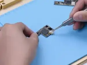
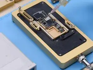
Remove thermal grease on the logic board and signal board. Attach the signal board to the holder. Dip rosin with Soldering Iron at 365℃ and solder wick to remove tin on the bonding pad. Remove tin on the logic board with the same method.
-
-
-
Clean the logic board with PCB Cleaner and remove the screw. Clean the signal board with PCB Cleaner.
-
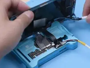
Attach the signal board and logic board to the Testing Fixture. Connect the screen to the motherboard with a Test Extension Cable. Connect the charging port flex cable and power cable. Then turn the phone on by connecting it with the computer.
-
Open 3uTools and view device details. The baseband version and Wi-Fi module can be read. It can be confirmed that the pseudo soldering causes the absence of the baseband version.
-
-
-
The next thing we need to do is to recombine the logic board and signal board. Put the signal board on the Reballing Platform. Put the Reballing Stencil in position. To prevent the solder paste from flowing into the motherboard crevices, insert a metal plate.
-
Apply a layer of low-temperature Solder Paste. Wipe off excess solder paste with an anti-static wipe. Remove the Reballing Stencil and signal board.
-
-
-
Put the signal board on the Heating Platform. Set the temperature to 180℃ to heat. After the solder balls are formed, turn off the power and cool the signal board. Apply some Paste Flux. Align the logic board with the signal board. Keep heating the motherboard at 180 ℃.
-
-
-
After recombination, install the motherboard on the phone. The phone can be turned on. Insert the SIM card. ICCID is showing. Because the phone has a network lock and we don’t have a SIM card of the carrier. No further tests can be conducted.
-
The iPhone XS had no service after being dropped. 3uTools couldn’t read the baseband version when we connected the phone to the computer. Through motherboard separation and testing the phone on the testing fixture, we confirmed that the no service trouble was caused by the pseudo soldering of the motherboard middle layer. ICCID came back to normal and the fault was cleared after we recombined the logic board and signal board.
