Einleitung
-
-
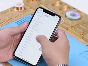
Go to Settings>Sounds&Haptics. All going well.
-
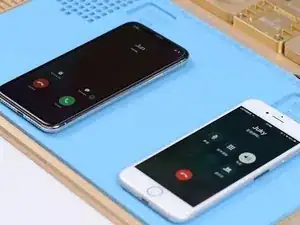
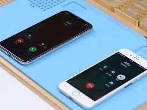
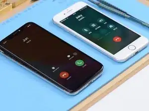
With the screen on, place a call to the phone using a known-good phone. The decline and answer buttons appear on the screen.
-
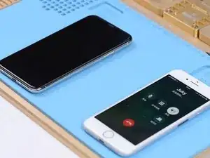
Turn the screen off. Place a call to the phone using a known-good phone. The phone is not responding at all. Press the power button to turn the screen on. We can see the decline and answer buttons on the screen.
-
-
-
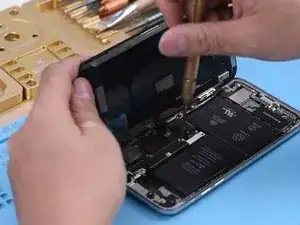
Judging by this, relevant circuits of the baseband wake signal might have malfunctioned. Take apart the phone and disconnect the battery. Remove the display assembly and take out the motherboard.
-
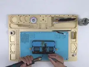
Attach the motherboard to the PCB Holder. Heat with Hot Air Gun at 200℃, air flow 3. Tear off the heat dissipation sticker on the backside of the motherboard.
-
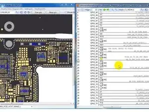
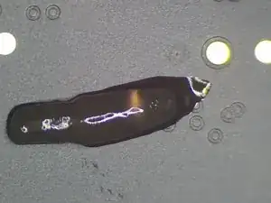
Open the bitmap software. Locate BB_TO_PMU_PCIE_HOST_WAKE_L. Since relevant circuits of the wake signal might have malfunctioned, we can try to borrow the wake signal from WiFi relevant circuits.
-
Locate WLAN_TO_PMU_HOST_WAKE. We can connect PP101_E-1 (the test point of the baseband wake signal) with PP7611_W-1 (the test point of the WiFi wake signal) by jumping a wire.
-
-
-
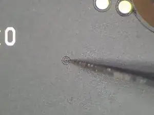
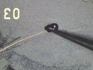
Scrape off the insulating coating on the two test points first. Then apply some solder paste to the two bonding pads. Heat with Soldering Iron at 365℃. Tin the two bonding pads with solder paste.
-
Connect PP101_E-1 to PP7611_W-1 with 0.02mm Enameled Copper Wire.
-
-
-
Then coat the wire with the UV Curable Solder Mask.
-
Now we can assemble the phone and test. With the screen off, test again. All going well. Fault cleared.
-
To reassemble your device, follow these instructions in reverse order.
