Einleitung
If your device stops working and you believe the problem is associated with the Motherboard, there is a way to fix it! Carefully follow these steps to remove and replace the logic board within the device, being sure to carefully place aside any parts. A soldering station is recommended for this procedure but is not necessary; just be sure to be cautious when removing the Motherboard from the device - it remains connected via small strip until the very last step. Happy fixing!
Werkzeuge
-
-
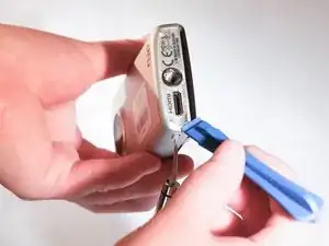
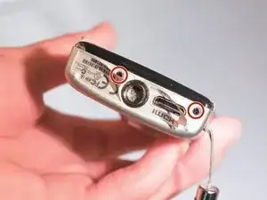
With the plastic opening tool, remove labels from the Flip Mino HD. 2 small black screws should appear.
-
With the Phillips Screwdriver 000, unscrew the 2 screws and set aside in a safe place.
-
-
-
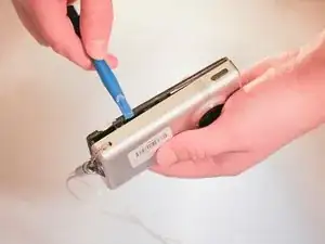
With the plastic opening tool, gently pry the front casing away from the device by carefully running the tool around each edge and lifting.
-
Once case is loose, flip up and over the device. Note that casing is still connected to the device.
-
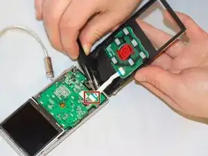
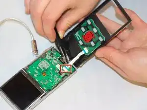
Using tweezers, pull connecting strip to disconnect it from its socket on the logic board.
-
-
-
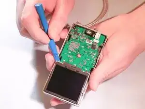
With plastic opening tool, take the display screen out of its socket by gently lifting each corner. Flip the screen up towards the Motherboard that it is still connected to.
-
Using the spudger, gently lift the film underneath the display bracket to peel it off. Set aside.
-
With the plastic opening tool, gently pry open metal display bracket to remove from the Motherboard.
-
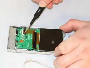
Using fingernail, pry black tape up from zif socket to remove the partially attached display screen.
-
-
-
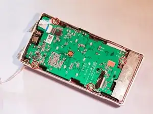
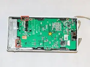
With the Phillips screwdriver 000 unscrew the 4 screws attaching the Motherboard to its outer casing and place safely aside.
-
Set up soldering station. At station, de-solder the leads of both microphones from the Motherboard.
-
With tweezers, gently pull the lead away as you heat up the joint with the tip of the iron. Do this for all 4 microphone leads.
-
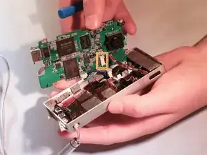
Gently pry the Motherboard out of its case, minding that the cords are still connecting the case and Motherboard. Remove the small black piece of tape that is securing the USB cable to the battery.
-
With tweezers, pull the USB ribbon cable connector away from its socket. Pull battery connector out of its socket on the logic board. The Motherboard should now be loose and free to remove.
-
To reassemble your device, follow these instructions in reverse order.
