Einleitung

This guide details the replacement for the Fluke 77 Series III Multimeter LCD. If the LCD is not working, the multimeter cannot display readings. This is the most difficult replacement for the device, but it is still a relatively easy replacement.

  1. UEZKvKN5G41RZp4e
    • Be sure any test leads are out and the multimeter is off before opening the device.

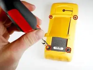
    • Turn the multimeter so it is display side down.

    • Lift up the back stand of the device by putting your thumb in the curved well at the bottom of the device, so you have access to the two covered screws below.

  2. pi1E4ATuCGeXiKsZ
    • Use your Phillips #2 Screwdriver to remove the four black 21 mm Phillips #2 screws.

  3. BmtZv6urRe3PgYdD
    BmtZv6urRe3PgYdD
    2VZUikyocuNNxpGE
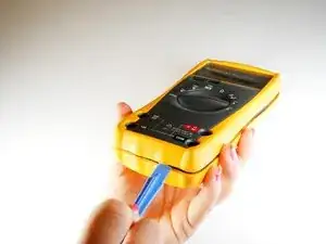
    • Turn the Fluke 77 Series III Multimeter back over so that it is display side up.

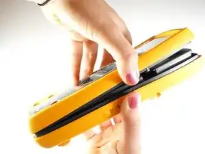
    • Pry the front panel from the back panel at the seam.

    • If the front panel does not come off easily, move a plastic opening tool along the seam until the panels separate completely.

  4. aFCBkPrNxCkAbQ5U
    aFCBkPrNxCkAbQ5U
    SATRvXmRmBieqxln
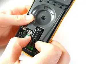
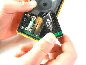
    • When doing this next step, make sure to remove the battery slowly, so you don't damage the wires connecting the battery to the device.

    • Locate the 9V battery in the lower right corner of the device.

    • Pull the battery out of its terminal.

  5. PyfZiBSKXyUGUcvD
    PyfZiBSKXyUGUcvD
    HAW4fRnIV1MuWGF2
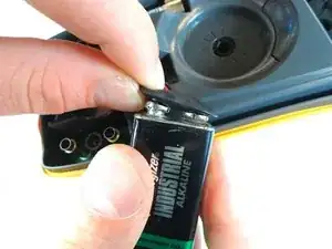
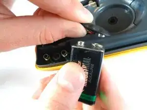
    • Only pull on the metal snaps and battery. Pulling the cords may damage them.

    • Detach the two metal snaps from the battery.

  6. PmRpVwONOOKtuVBa
    PmRpVwONOOKtuVBa
    FedRHNDsHRSLWnkV
    • Replace a fuse only with a fuse identical in type, voltage rating, and current rating as specified by the back panel fuse rating label or the Fluke 77 Series III Service Manual. Inserting the wrong replacement fuse could create a fire hazard.

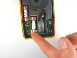
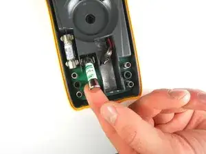
    • Locate the fuses near the bottom left corner inside the device.

    • Take note of which fuses belong in which location before removal. They are NOT interchangeable.

    • The .440 Amp fuse is located in the upper left hand fuse holder.

    • The 11 Amp fuse is located in the lower right hand fuse holder.

    • Lift the rounded edge of the fuse with one finger until that side is completely out of its holder.

  7. YsKLKVGAVQoNQC2G
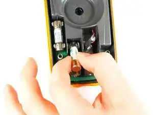
    • Grab the lifted edge of the fuse between your thumb and forefinger and pull it the rest of the way out of the device.

    • The fuse in the upper left corner can be tricky to remove. Use a plastic opening tool if needed.

    • Repeat steps 4 and 5 to remove the other fuse if you are replacing both fuses or if you are replacing a different part further on.

  8. l1lx2wPZE1WTL3Vo
    l1lx2wPZE1WTL3Vo
    QKHXIloW1JblJu4d
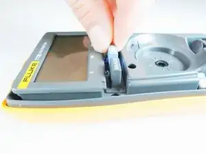
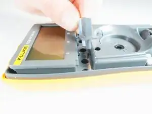
    • Locate the rubber range and hold buttons in the internal assembly. These are found just below the LCD screen on the left hand side.

    • The buttons are attached so they will come out of the multimeter as a single part.

    • Remove the rubber range and hold button part with your thumb and forefinger.

  9. WbqDgQwDPOkWFNJU
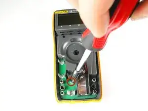
    • Locate the silver 7 mm screw found underneath the 11A fuse.

    • Using the Phillips #0 Screwdriver, unscrew and remove the silver 7 mm Phillips #0 screw that attaches the back panel to the internal cover.

  10. 1ZMeATdbXSoqqmsH
    • Lift the grey internal cover out of the back panel.

    • You should now have the grey internal cover that's connected to the PCA circuit board and the plastic back panel in two separate pieces.

  11. IZc6ApgSWhHl1fMv
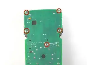
    • Turn the internal assembly over so that the green circuit board (PCA) is visible.

    • Locate the five silver 11 mm Phillips #1 screws on the upper part of the circuit board that hold it to the the grey plastic internal cover.

  12. SFKXAxgQdXShVeyL
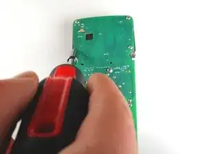
    • Use the Phillips #1 Screwdriver to remove the five silver 11 mm Phillips #1 screws attaching the green circuit board to the grey plastic internal cover.

  13. piUa6vsbaCx6DIZD
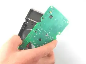
    • Do not touch any of the chips on the underside of the circuit board because static electricity on your hands could damage them.

    • Carefully lift the circuit board up and away from the internal cover.

  14. ZMBZYF5Vgs4qMKlI
    ZMBZYF5Vgs4qMKlI
    xpflXROaDKCYnW6c
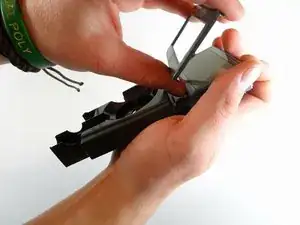
    • Turn the internal cover over with both hands.

    • Pry off the LCD screen bracket bordering the display.

  15. 2Z23b1OSH2LrZrCC
    2Z23b1OSH2LrZrCC
    gLWpJnCV1UWMFecC
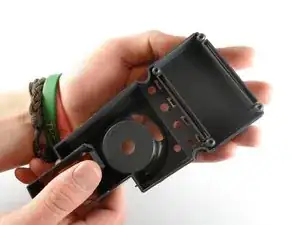
    • Cover the LCD display with one of your hands.

    • Turn the internal cover over so that the LCD display is face down.

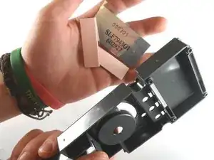
    • Slowly pull up the internal cover. The LCD display should fall right into your hand.

    • Use the text on the back of the LCD as reference for the orientation of the replacement LCD in the multimeter. The multimeter will not display correctly if the LCD is inverted.

    • The two pink rubber serial wire holders may fall out of the slots above and below the LCD slot in the internal cover. If this happens, simply put them back in their slots during reassembly.

    If the display is erratic, you may only have to replace the rubber conductors. Cleaning them may be good enough

    Tom Karches -

Abschluss

To reassemble your device, follow these instructions in reverse order.

Jessica Bombardier Shaw

Mitglied seit: 30/01/14

1006 Reputation

5 Kommentare

Great job! Ive found that sometimes all it takes to get the LCD working again is to clean those pink rubber conductors and with isopropyl alcohol.

Chris Barth -

What is the LCD part #? And where to buy?

Zach -

Good job .. can i make replacement display from fluk 179 to fluke 77 series 3 .. there are the same size with different model .. thank you

Ahmed Vaio -

I just cracked the screen on my Fluke 79 III and this repair guide will be invaluable. If anyone can offer a part number for the screen or where I could buy one, I would be most appreciative.

Ladd Morse -

FLUKE 1560856 for 175/177/179 Multimeters

https://www.tme.eu/ie/en/details/flk-pn1...

Peter Farrington -