Einleitung
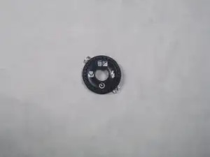
In this guide, readers will be taught how to take apart the Fujifilm Finepix F505EXR camera with a Philips head screwdriver and reach the selector button. It will then be shown on how to take out and replace the selector button. The selector button is used to select various tasks on the camera including deleting pictures. If this feature does not work it may be hard to clear up storage.
Werkzeuge
-
-
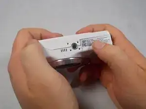
Hold the camera with the lens facing towards youself.
-
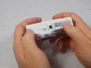
Turn the camera upside down and place your right thumb on the battery chamber cover.
-
-
-
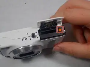
Hold the camera, then pull the battery chamber towards yourself with your right thumb.
-
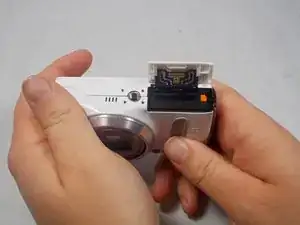
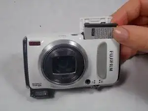
Pull the cover entirely out and release it to reveal the battery.
-
-
-
Locate the orange battery latch that holds the battery in place.
-
Use your finger to push the latch away from yourself to release the battery.
-
Remove the battery manually from the battery chamber.
-
Place the battery into a charger if it is dead.
-
-
-
Replace defective battery if previous steps fail
-
Contact support on the Fujifilm website for further assistance
-
-
-
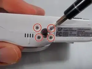
Remove four 2.5mm Phillips #1 screws on the bottom of the camera near where the camera mount attaches.
-
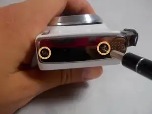
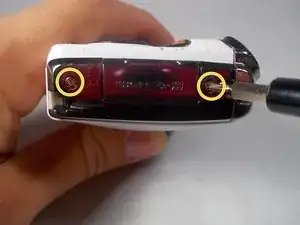
Remove two 5.1mm Phillips #1 screws on the left side of the camera relative to the LCD screen.
-
Remove two 5.1mm Phillips #1 screws on the right side of the camera relative to the LCD screen nearest to the mode wheel.
-
-
-
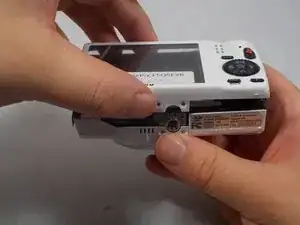
Place the camera lens face down with the LCD screen face up on a flat surface, or hold it. Carefully lift the camera’s back cover approximately 1 inch.
-
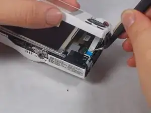
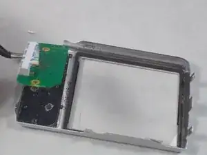
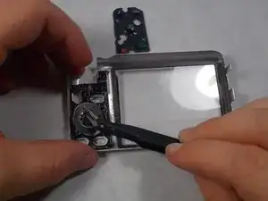
Carefully lift the ribbon clamp connector back using the tweezers and remove the blue ribbon.
-
-
-
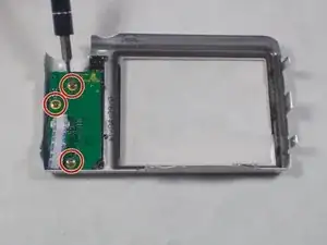
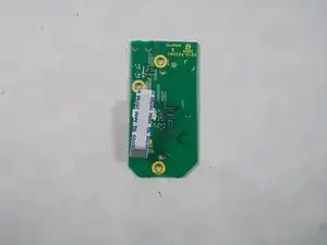
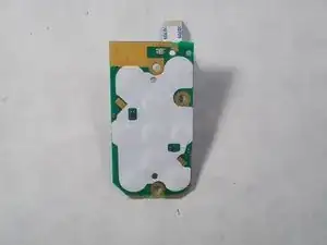
After the selector button circuit board is taken out. There will be a black rubber display for the front buttons, remove this.
-
-
-
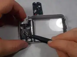
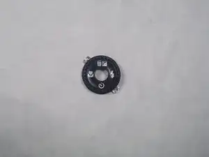
After taking the rubber button selector out, there will still be a circular metal selector button. This is what makes the camera delete pictures and do various tasks. Remove this and set aside.
-
To reassemble your device, follow these instructions in reverse order.
