Einleitung
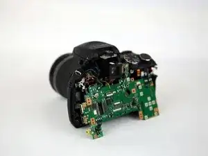
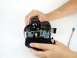
This guides is meant to be used with the intention to replace the motherboard, which is the central part of the camera.
Warning: As the motherboard plays such a central role in the camera's function, the many wires and cables that connect the many parts to the camera together can be damaged in the replacement process. To avoid any excess damage, treat all wires and cables with care.
Werkzeuge
Ersatzteile
-
-
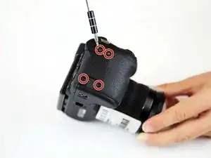
Flip the camera so that it is now upside down.
-
With a screwdriver, unscrew all highlighted screws.
-
-
-
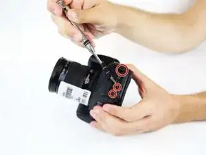
Flip the camera so that it is now on the right side.
-
With a screwdriver, unscrew all highlighted screws.
-
-
-
Flip the camera so that it is now on the left side.
-
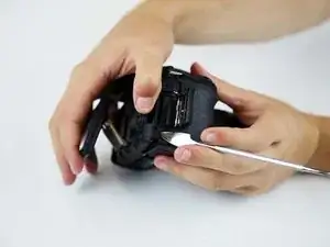
Move or remove the flap hiding the camera ports.
-
With a screwdriver, unscrew all highlighted screws.
-
-
-
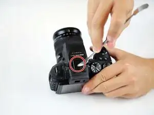
Flip the camera so that it is now on the top side.
-
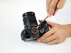
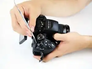
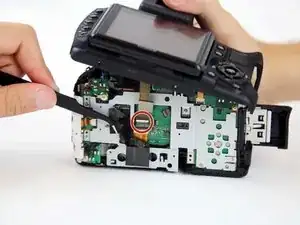
With a spudger, pry off the highlighted metal piece of the camera.
-
-
-
Pull the LCD Screen up and out of the way.
-
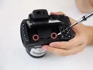
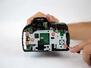
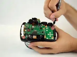
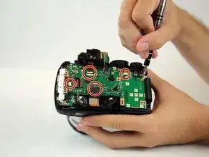
With a screwdriver, unscrew all highlighted screws.
-
-
-
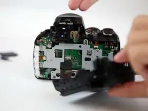
Peel back (or off) the black tape to expose more of the inside of the camera.
-
Flip the white switch of the highlighted chamber up, and that should unlock the ribbon cable from its compartment.
-
To see if this worked, gently pull the ribbon cable out of the compartment. It should come out without force.
-
-
-
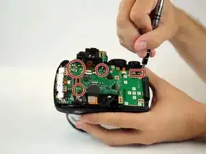
Ensure the two ribbon cables highlighted are disconnected from the motherboard. (One is under the black tape.)
-
-
-
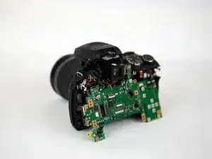
Remove the motherboard
-
If your intention is to replace the motherboard, put your new motherboard in and begin re-soldering all cables back to the new motherboard.
-
To reassemble your device, follow these instructions in reverse order.
2 Kommentare
have you instructions to remove power on and selector assembly?
have you istructions to remove the poweron switch asm. for the hs30exr?
