Einleitung

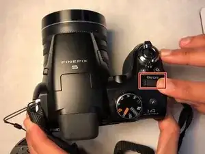
  1. hv31CFcsE4qKfpDg
    • Turn off the camera by pushing the switch as shown.

  2. qDgHTw6p12ReTBeI
    qDgHTw6p12ReTBeI
    LMEemVhy4iCe65Ty
    UWILBRQ534VTQdKC
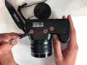
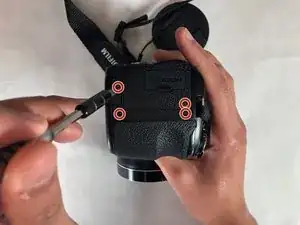
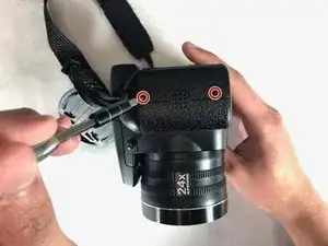
    • Remove all the 4mm screws from the left, right, and bottom of the camera.

    • A Phillips #000 screwdriver should be used to remove all nine screws.

  3. vpcAgFidjroG6HuU
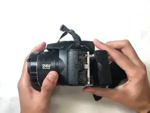
    • Remove casing part pictured by gently pulling up until casing is fully detached.

  4. x6oBu2fMbc2F31A5
    x6oBu2fMbc2F31A5
    DBhvodJEIjhWtRBY
    YdGyZkfvQj1imLK1
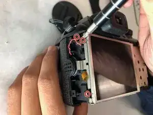
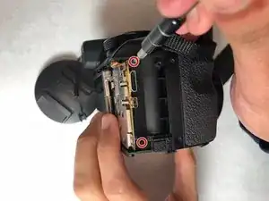
    • Remove the 4 mm screws on the metal plate. Then remove the 4 mm screws on left side of the camera, and remove the two 4mm screws on right side.

    • Use the Phillips #000 screwdriver to avoid stripping the screws.

  5. 2uiSX3KCA6rseWHK
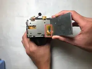
    • Remove the top casing by pulling upwards.

    • To remove orange tab gently pull on the tab until it is detached from the clamping device on the motherboard.

  6. LbmbkXaLr6AGLt6R
    LbmbkXaLr6AGLt6R
    cb5vTnW4Fk5vKnjq
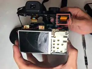
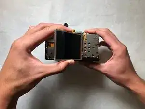
    • Carefully remove LCD screen.

    • Gently pull on orange tab until it is free.

    • This orange strip is susceptible to tearing.

  7. CxodSk3lSGMy3aRc
    CxodSk3lSGMy3aRc
    wsFoACyhSFSKPVOC
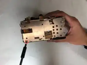
    • Remove remaining 4mm screw.

    • Detach metal plate by lifting plate upwards.

  8. b1m52VoVSTsm4Qy6
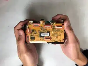
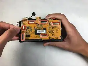
    • Remove remaining orange tabs on motherboard. Gently pull on each orange tab until it is free. Make sure all tabs are free (check markers on image).

  9. AbEVaEqrbw6jFFVF
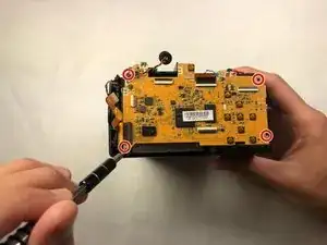
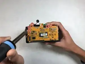
    • Remove the 4mm screws in the corners of the motherboard.

  10. wiCuhmlaIsaW322b
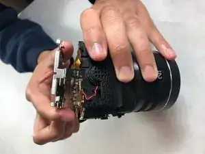
    • Use a soldering iron to melt the solder and disconnect the five connections shown.

    • After removing the soldered connections, they must be given ample time to cool before moving to the next step.

  11. YElS3HKywHVP3fq4
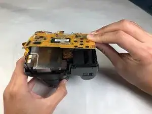
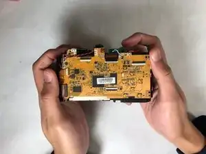
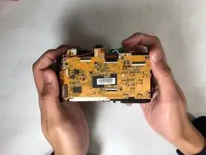
    • Remove the motherboard. It should be free of all connections at this point and can be lifted with ease.

  12. RZHLg3XIncdCJRpj
    • Replace the old motherboard with a new motherboard.

  13. 4cnaS5weGcdoEFl2
    • Reconnect the orange strips to their designated connections.

    • Be gentle when reconnecting the orange strips as they are susceptible to tearing.

  14. uCNDU1uGCLAIYWBT
    • Resolder all the connections and wire onto the new motherboard

    • After soldering the connections, they must be given ample time to cool before moving to the next step.

    • After given enough time and all the connections on new motherboard are secured, reassemble the camera.

Abschluss

To reassemble your device, follow these instructions in reverse order.
Marisol Montes-Castro

Mitglied seit: 31/10/18

229 Reputation

0 Kommentare