Einleitung
Werkzeuge
-
-
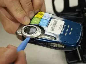
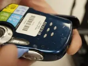
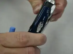
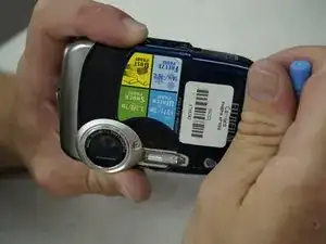
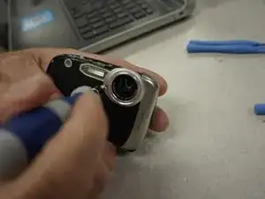
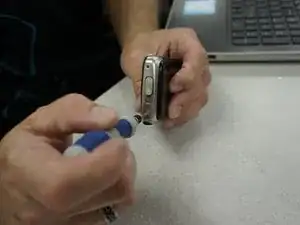
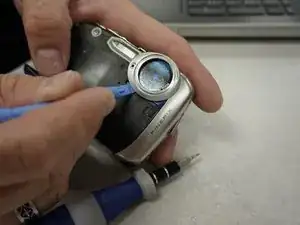
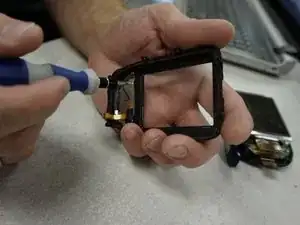
Use a screwdriver to remove the four screws from the top and bottom of the camera. Remove the screws securing the lanyard as well.
-
Use a T5 Torx bit to secure the exterior decorative cover of the device.
-
-
-
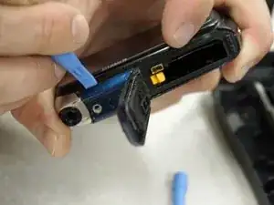
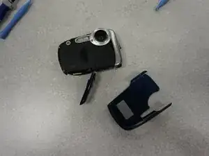
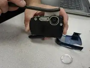
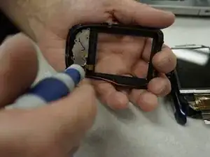
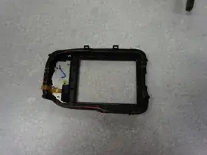
Locate the securing tabs of the housing unit.
-
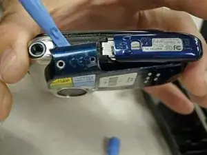
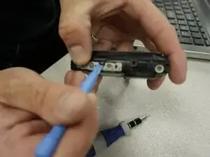
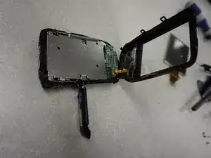
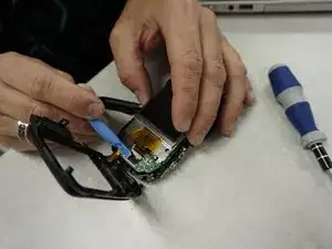
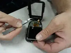
Using the spongerslowly work your way around the outside of the case using the sponging tool to pry open the case.
-
*** Take extreme caution when doing this being careful not to break the securing tabs of the housing.
-
-
-
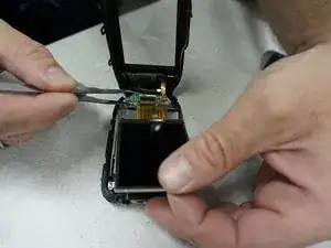
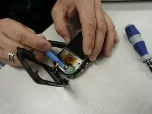
Once the case is open locate the Ribbon cable attachment for the LCD screen.
-
Carefully ensure that the LCD screen is free from all attachments and any tape securing the ribbon cable is released.
-
-
-
Gently lift up on the black securing bar of the ribbon cable in order to free it from the units motherboard, thus releasing the LCD from the computer.
-
-
-
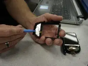
Locate the ribbon cable attachment for the rear panel controls.
-
Gently lift the ribbon cable securing bar and slide the ribbon cable from the socket in order to remove the rear control panel.
-
-
-
Locate the six screws on the control panel.
-
**two of the screws may be covered by tape. Remove the tape to access them.
-
Use the PH000 Phillip’s screwdriver bit from the Ifixit driver kit to remove the screws and free the control panel from the unit.
-
To reassemble your device, follow these instructions in reverse order.
