Einleitung

This guide will help you replace the LCD screen on the Fujifilm X-M1.

We highly suggest you use a magnetic project mat or an organization tray. This camera has many different types of screws and keeping them organized is key to proper reassembly.

  1. HUuVPB5nGXimig4I
    HUuVPB5nGXimig4I
    NKi13DXVRHh2WYYk
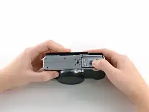
    • Turn the camera upside down to locate the battery compartment.

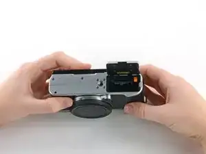
    • Slide the button up to open the compartment.

    • Slide the orange button up to release the battery.

    • The battery is not shown in these photos.

  2. pmAGJtMjZBGOHgxx
    pmAGJtMjZBGOHgxx
    Q4SaTEDC6qUFJuIM
    OZKJMexwSHZJTvFC
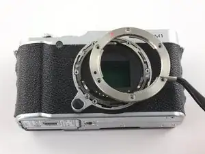
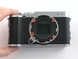
    • Twist the lens cap to remove it from the camera.

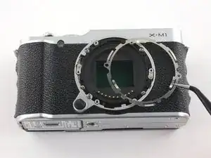
    • Remove the six 6.5 mm Phillips screws from the front of the lens assembly.

    • Use tweezers to remove the top metal ring and the thin metal ring below it .

    Hi! Thanks for the wonderful guide, just want to comment here that I found out that you can skip both Step 2 and also Step 3 if you just want to replace the LCD screen, cheers!

    ikhsan.zohri -

  3. J4TKwcDqKyhHrwaL
    • Remove the four 4.3 mm Phillips screws inside the lens assembly.

  4. WG2aER25jFbwnOQP
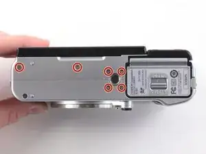
    • Remove the six 2.5 mm Phillips screws from the bottom of the camera.

  5. KQCSAfXhajBPMQft
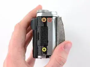
    • Use tweezers or a finger nail to peel back the rubber cover on the left handgrip.

    • Remove the 3.4 mm Phillips screw.

    • Remove the 3.7 mm screw.

  6. GUORcUyOmsx2ibjW
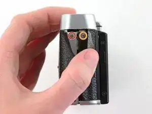
    • Use tweezers or a fingernail to peel back the rubber cover on the right handgrip.

    • Remove the 3.2 mm Phillips screw.

    • Remove the 3.8 mm Phillips screw.

    • Remove the 2.8 mm Phillips screw.

  7. WPk3CgI1LtKaXVwK
    WPk3CgI1LtKaXVwK
    2PddbDegErKYWIOu
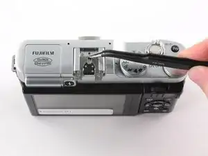
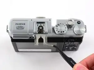
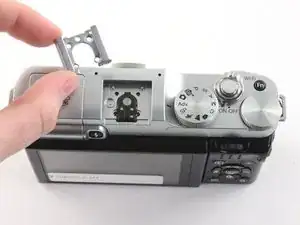
    • Use tweezers to slide the metal shield straight out of the external flash mount.

  8. rUTBAwgvwbJalsFa
    rUTBAwgvwbJalsFa
    ynSFTqfJcL1EiJsw
    Z1BFIoBQyJZ3bXM3
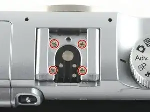
    • Remove the four 4.6 mm Phillips screws from the external flash mount.

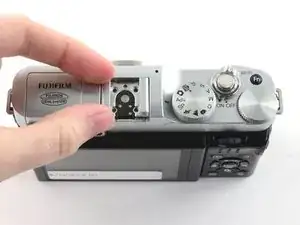
    • Use tweezers or two fingers to remove the mount clip.

  9. bbYWWCXCtRmxp6Pr
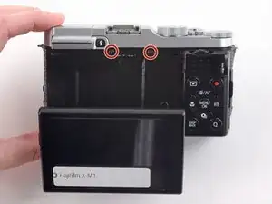
    • Extend the LCD.

    • Remove the two black 4.3 mm Phillips screws from the back case.

  10. QfZsDqRZ6xVGlbbM
    QfZsDqRZ6xVGlbbM
    YTrVTOe5XcXDEboo
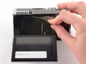
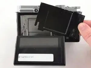
    • Use two fingers to peel back and remove the black plastic cover from behind the LCD.

  11. xEUwtEijALdvnj11
    xEUwtEijALdvnj11
    fCnALSPbUOQxqnEC
    hjLCJokiKTGthKd3
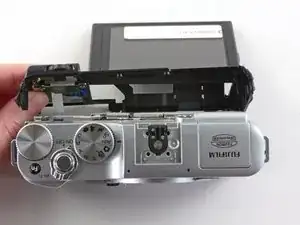
    • Slowly pull the back frame away from the camera.

    • Do not attempt to remove the frame, as it is attached to the camera by a ribbon cable.

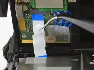
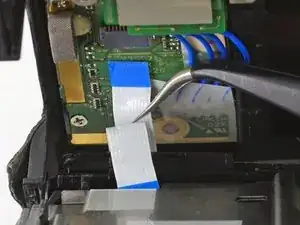
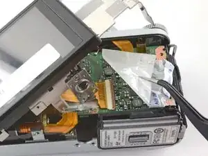
    • Use tweezers to pull the white and blue ribbon cable out of the connector.

  12. TvghfGEyEnIJMTs6
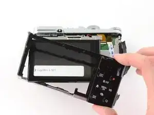
    • Slide the frame around the LCD to remove it from the camera.

  13. dopMGLCOVFESAcoJ
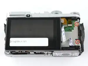
    • Remove the two 2.6 mm Phillips screws from the right side of the metal frame.

  14. lkZr2gfj1O6KaNbe
    lkZr2gfj1O6KaNbe
    t41oQDxA3p5REU2t
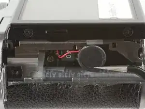
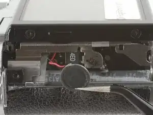
    • Use tweezers to unhook the speaker near the left handgrip.

  15. IWhnhTPLMXXvBFPc
    IWhnhTPLMXXvBFPc
    1CsQlmsXUC1OrDbY
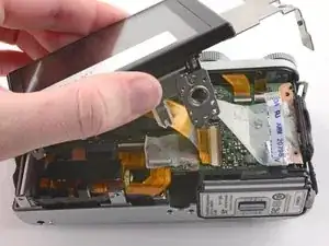
    • Slowly lift the metal frame away from the motherboard.

    • Do not attempt to remove the frame, as it is attached to the motherboard by a large ribbon cable.

    • Use tweezers to remove the plastic covering the motherboard.

  16. asXYllBOd2OAeQjO
    asXYllBOd2OAeQjO
    y43cv5vBQnbP6hn5
    FSnYcwaPbEfmFtBZ
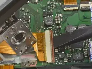
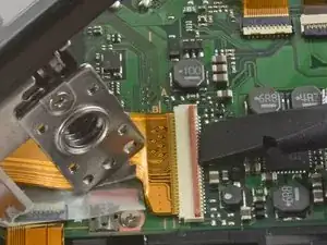
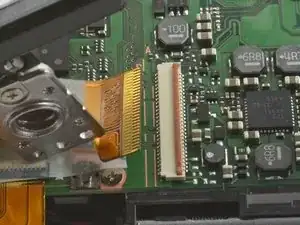
    • To remove the ribbon cable, flip back the orange lock on the large ZIF connector with the flat end of a spudger.

    • If the ribbon cable does not pop out on its own, use tweezers to pull it out of the connector.

    • Remove the back case.

  17. ir3MBkSLV4XlrGpe
    ir3MBkSLV4XlrGpe
    3giZwlFcytPbg4eS
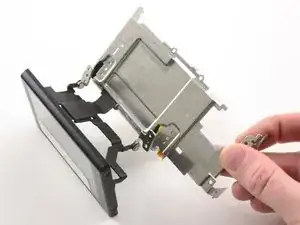
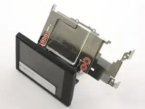
    • Remove the four 2.6 mm Phillips screws from the LCD hinges.

    • Tilt the LCD away from the metal frame.

    • Do not attempt to remove the LCD, as it is attached to the metal frame by a ribbon cable.

  18. FJyqejOKGOoCLhmi
    FJyqejOKGOoCLhmi
    I2TLTF2536kaAlfF
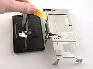
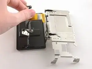
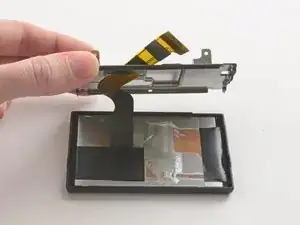
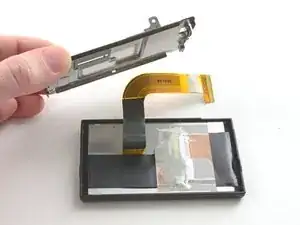
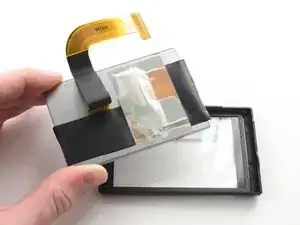
    • Use two fingers to pull the ribbon through the hole in the metal frame.

    • Remove the LCD from the metal frame.

  19. QJ4xols2ce3nSfN5
    QJ4xols2ce3nSfN5
    UcpTObJgCBsxAp1y
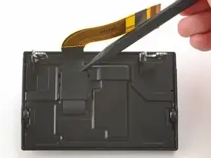
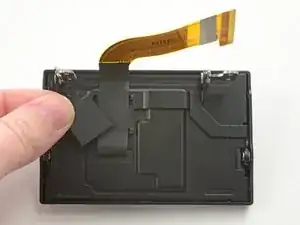
    • Use the pointed end of a spudger to remove the ribbon cover on the back of the LCD.

  20. AunGNcgypUockcDc
    AunGNcgypUockcDc
    bgnd3psCrWIiF1Ly
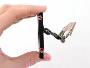
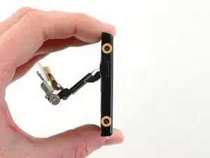
    • Remove the two 2.6 mm Phillips screws from the right hand side of the LCD screen.

    • Remove the two 2.6 mm Phillips screws from the left hand side of the LCD screen.

  21. B4bBCAyfareQPDsB
    B4bBCAyfareQPDsB
    XqusUaume2SBBQRZ
    fTAw4XYIC1L6xBxP
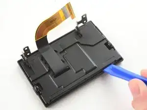
    • Use a plastic opening tool to pry the LCD case open.

    • Once the case is open, pull the ribbon through the hole on the back case.

  22. dOUpIW1OPDRbvQVo
    • Remove the LCD from the screen cover.

Abschluss

To reassemble your device, follow these instructions in reverse order.
Kelsea Weber

Mitglied seit: 12/11/15

19058 Reputation

0 Kommentare