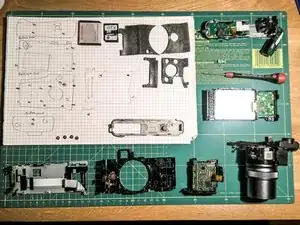
Einleitung
Werkzeuge
-
-
Remove the battery and the SD-Card.
-
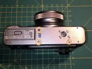
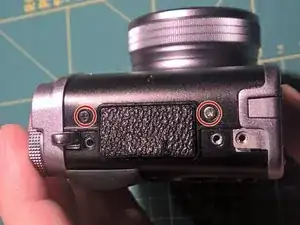
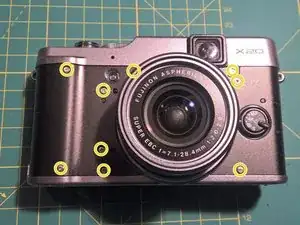
Remove the three marked screws from the bottom of the camera.
-
-
-
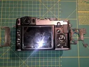
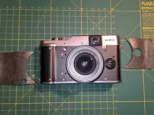
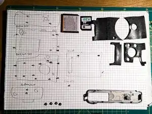
Remove four pieces of leatherette from the front and the back of the camera. Lift the edge of the leatherette and pull. The material itself is quite sturdy and the glue will still be good if you re-apply the pieces after you are finished.
-
-
-
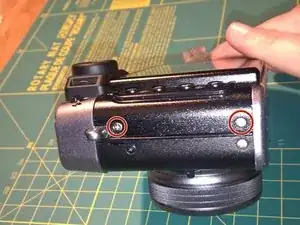
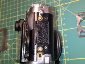
Remove two screws from the left side of the camera
-
Remove three screws from the right side of the camera
-
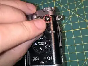
Remove the screw between the Q and the DISP/BACK button.
-
-
-
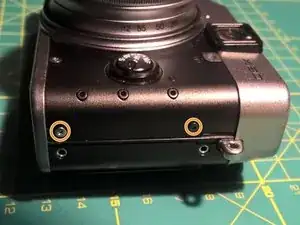
Remove two screws from the left side of the camera.
-
Remove two screws from the right side of the camera
-
Remove nine screws from the front of the camera.
-
-
-
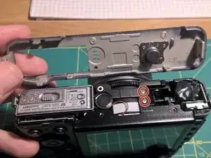
You can now remove the plastic base cover.
-
Below you will see two more screws. Please remove them as well.
-
-
-
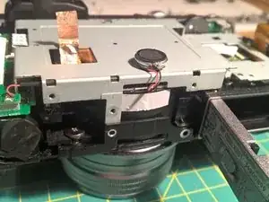
Now the two metal covers will get loose. Start by removing the back-cover containing the LCD.
-
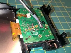
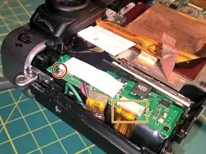
Open the connector holding the FPC (the orange wiggly thing) and remove it.
-
You open the connector by lifting the little clip on the opposite side of the oranged FPC (second picture). Then you can pull out the orange FPC.
-
-
-
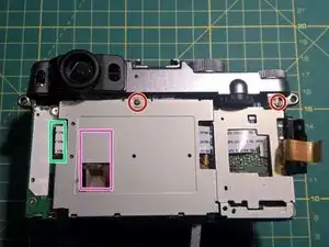
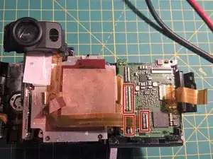
Remove two screws (red).
-
Disconnect the FPC on the left side (green rectancle). You have to open the lever.
-
Remove the copper foil from the upper part, but do not remove it completely (pink rectangle).
-
The small round part on the bottom is the beeper. Free the connecting wire from the white duct tape. The beeper itself is glued in his place and can easily be removed by pulling.
-
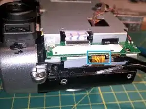
On the left side is one FPC left. This connector can not be opened, the FPC must be removed by pulling (blue-ish rectangle)
-
-
-
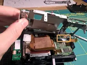
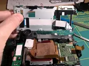
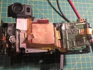
Finally! You can move the steel part away and by opening the last remaining FPC connector on the main PCB you can remove this steel thing completely.
-
-
-
Remove the screw below the white plastic.
-
Remove the lower FPC as well. This connector does not have a lever. Remove the cable by pulling.
-
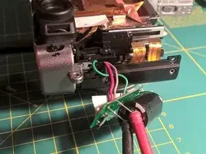
You can now remove the little PCB from the housing.
-
-
-
Ok, only two steps, then the top-cover can be removed.
-
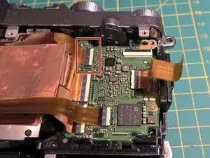
First, remove the marked FPC from its connector. This leads to any button or wheel on the silver top part.
-
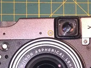
The remove the tiny screw beneath the viewfinder on the front with an TORX T1.
-
Then you can remove the silver top cover by pulling.
-
The big capacitor will still be attached.
-
-
-
Separate the right PCB by disconnecting the remaining three FPCs.
-
This part (PCB and containing plastic) can now be removed as well.
-
-
-
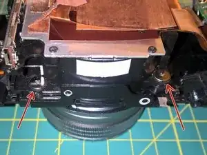
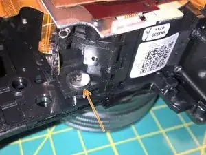
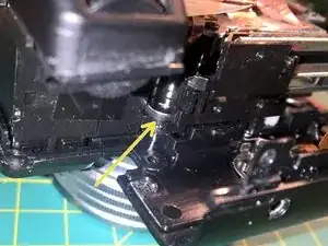
The lens is screwed with four big screws to the body.
-
Two screws on the bottom are easily accessible
-
One screw on the top left is also easy to reach.
-
The fourth screw is a bit hidden under two FPCs. You don't have to remove these FPCs to remove this screw.
-
-
-
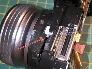
I found some sand lodged between the big and the little gear shown on the picture. I turned the lens so that the opening pointed down and carefully turned the lens back and forth. A very small amount of sand fell out but it was enough to get things going again.
-
To reassemble your device, follow these instructions in reverse order. Please pay attention to the following steps:
-On the PCB with the big capacitor you have to push the FPC in. There is no lever on the socket.
- On all other sockets, open the lever first, slide in the FPC and close the socket.
- Be careful with the thick wires going to the flash, They may keep keep the flash from opening. Try this out before closing the camera.
- Don't forget so secure the beeper and his wire.
- Also remember to glue on the copper foil.
