Einleitung
Werkzeuge
-
-
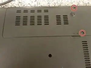
Remove the two Philips screws securing the hard drive cover to the base.
-
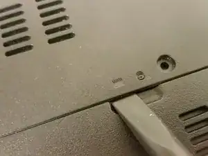
Pry the hard drive cover off with a spudger.
-
-
-
Push the clips away from each other that are holding the RAM sticks. The RAM will then pop upwards. At this point, you can pull the stick out. Repeat for the second stick if applicable.
-
-
-
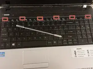
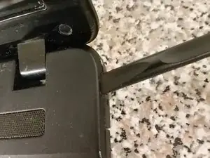
Use a fine spudger to push all six keyboard tabs. On the first, you'll have to use a bit of prying to get under the keyboard. After that, get your fingernail under the keyboard, and pull gently as you go along the keyboard using the spudger to pop the other clips.
-
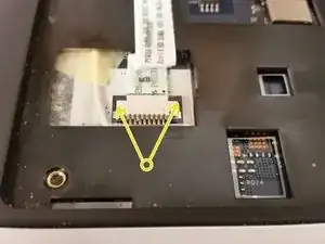
Gently push each side of the locking connector's lock towards the screen, and then pull the now-loose keyboard cable out. Set the keyboard aside.
-
Gently push each side of the power button locking connector towards the screen, and then pull the cable out.
-
-
-
Flip the laptop over again.
-
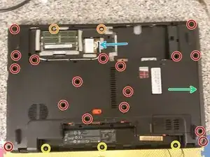
Remove the seventeen Philips M2.5x8 screws securing the palmrest.
-
Remove the two silver Philips M2.5x6 screws securing the palmrest.
-
Break out the Philips #0 bit, and remove the three silver Philips M2 screws securing the palmrest.
-
Use a spudger to separate the palmrest from the base.
-
Slide the optical drive out.
-
Remove the wireless antenna connectors, and then the wireless card.
-
-
-
Back with the Philips #1 bit, remove the two silver M2.5x6 Philips screws.
-
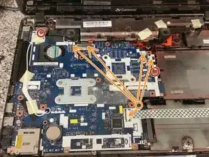
Remove all cables from the motherboard, including pulling out the wireless antenna from its hole.
-
Flip the motherboard up. The DC jack is still connected to the board, so don't tug the board away just yet.
-
-
-
Pull back on the DC jack plug to remove it. Now you may remove the motherboard and put the rest of the laptop aside.
-
-
-
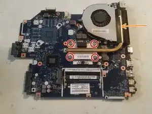
Remove the four screws securing the heatsink to the motherboard.
-
Remove the black tape securing the heatsink to the fan, and now the heatsink will be free.
-
-
-
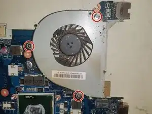
Remove the three screws securing the fan to the motherboard.
-
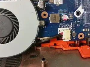
Remove the fan connector from the motherboard, and then remove the fan.
-
-
-
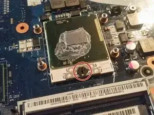
Turn the CPU socket screw counterclockwise to release the CPU, and lift the CPU out of the socket.
-
-
-
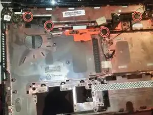
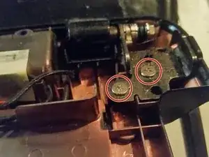
Remove each of the screws securing the hinges to the base, and then lift the assembly upwards to remove it.
-
-
-
At this point, you may simply pull upwards on the DC jack to remove it.
-
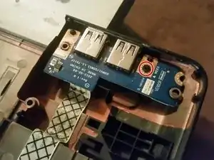
The USB port board is secured by a single M2x3 Philips screw. You may remove this screw and pull the board by its cable upwards.
-
To reassemble your device, follow these instructions in reverse order.
