Einleitung

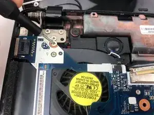
If your motherboard is defective or you are looking to upgrade your Gateway laptop, this guide will show you how to remove your motherboard. Upgrading your motherboard can allow your device to run a faster CPU, faster RAM, faster data transfer, or a better graphics card. Your motherboard is responsible for making all of your device’s components work together, so make sure that all components you may be changing are compatible.

  1. exIMORKXLLKFj5to
    exIMORKXLLKFj5to
    6lPNprcRYGTBiIUZ
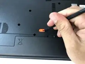
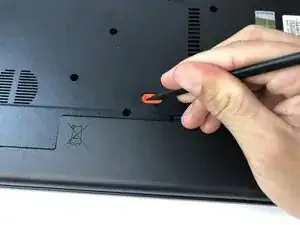
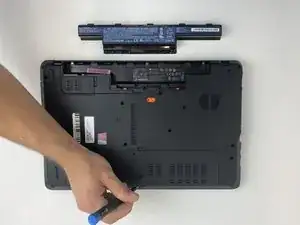
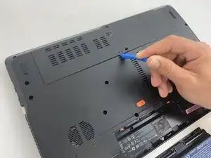
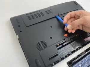
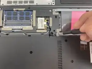
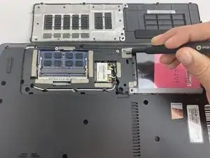
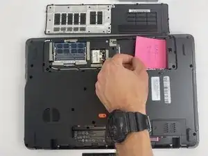
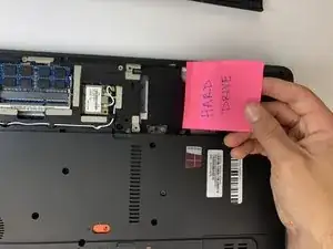
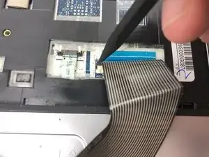
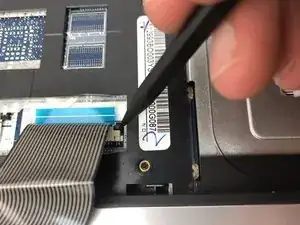
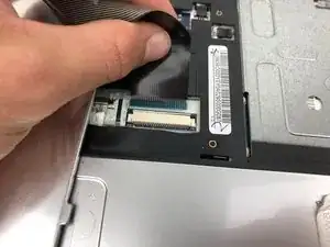
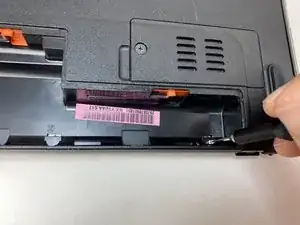
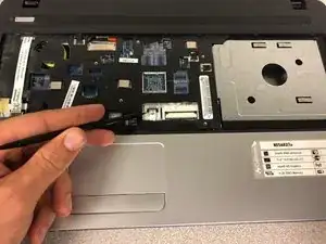
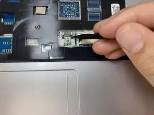
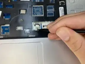
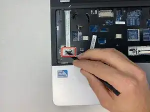
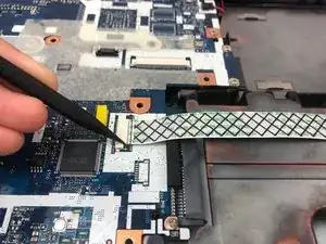
    • Using the spudger, push the orange tab to the unlock position.

    Do you have shots of before and after? For this kind of step, iFixit prefers flipbook style shots.

    Alex Watkins -

    You also used the screwdriver, not the spudger, in the image. Be sure to appropriately identify tools.

    Alex Watkins -

  2. GJgm5KPZTRTSZV31
    GJgm5KPZTRTSZV31
    XldfDsXDJnACBwTW
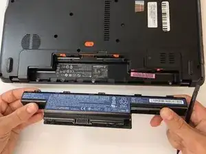
    • Lift the battery from its compartment.

    • When reinstalling, insert back end of battery first, then clicking into place.

    As before, include multiple shots to demonstrate how to do this. Also, since you’re not using the screwdriver, I would not include it in the background here.

    Alex Watkins -

  3. 3y4avtC4qNOOHQLu
    3y4avtC4qNOOHQLu
    xPfSeNauyDfjr6ju
    M3YDSXOuCerFAoDW
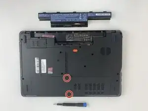
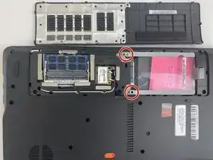
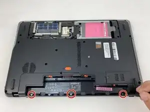
    • Unscrew the two 7.9mm Phillips #0 screws that secure the service cover.

    Take pictures from first person perspective, rather than as if you’re watching the repair.

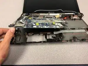
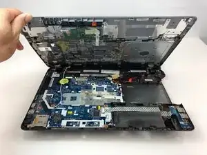
    Alex Watkins -

    Make sure to use appropriate bullets to match markup. What size are the screws?

    Alex Watkins -

  4. XmX6KjVBAPoFTwHk
    XmX6KjVBAPoFTwHk
    Wq63n5RTOF1pk5N5
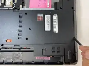
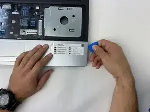
    • Use the opening tool to gently pry open the compartment covering.

  5. Y1EVsiqlVlBJoxAd
    Y1EVsiqlVlBJoxAd
    qiRoM4XYOCFjJ2cQ
    VPbNKBaI1GJciom1
    • Unscrew the two 0.5mm screws from the hard drive brackets using the Phillips #0 screwdriver.

    • Pull the plastic tab attached to the hard drive to the right to remove the hard drive.

    • The hard drive plugs into the port on the left within the compartment. Be sure to gently remove the hard drive without damaging the port.

    For all screws, you need to include the measurements.

    Alex Watkins -

    Also, be sure to always use the appropriately colored bullets to match markup. I’m not marking additional instances of this issue, so be sure to check throughout.

    Alex Watkins -

  6. WRoTg12DRXU2EbdE
    WRoTg12DRXU2EbdE
    JtsUBkhSsVvWGuQt
    • Remove the hard drive by lifting up the right side, releasing the hard drive from the compartment clips on the left.

    Can you add a final image of you removing the “hard drive” here?

    Alex Watkins -

  7. eISxraRyDiYcIFLK
    eISxraRyDiYcIFLK
    iRgNemO1LBiDaNfW
    • Flip your laptop over to view the keyboard.

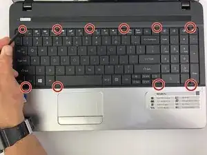
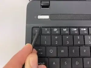
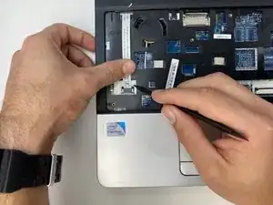
    • Using the spudger, push in the ten tabs at the edges of the keyboard.

    How many of the tabs are there? Where are they located? I would add a top down shot to mark up where all the tabs are located.

    Alex Watkins -

  8. RMBZIBNgwyYsDKGE
    RMBZIBNgwyYsDKGE
    QVEDKBT2FbtpVYlv
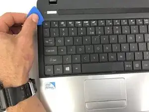
    • Using the opening pick, lift the edges of the keyboard.

    • Repeat around the edges of the device.

    • Lift up the keyboard to expose the cables underneath.

    I think that step 8 and step 9 could be combined here.

    Alex Watkins -

  9. 4gfwtyjPhbZVLUKK
    4gfwtyjPhbZVLUKK
    xZWBESJUYTAjNsZ2
    DC1CHoQISsRZABam
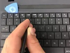
    • Release the clamp holding the mini-DIN cord by lifting the two black tabs on either side.

    • Gently pull the mini-DIN cord out of the clamp.

    • Remove the keyboard.

    Be sure each step is a command. What are you asking the user to do in the first bullet?

    Alex Watkins -

    The last picture seems to change the orientation, which is a little confusing for me. Try to maintain the same perspective.

    Alex Watkins -

  10. HxLL6ZFMuqTUeMIR
    HxLL6ZFMuqTUeMIR
    EnfI5yBHtkMGLCGJ
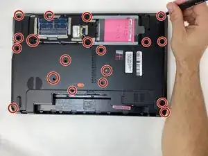
    • Using a Phillips #000 driver, remove the three silver 0.79mm screws located on the back edge of the battery compartment.

    These images have a very heavy shadow on them. I would try to budget time to retake the motherboard pictures.

    Alex Watkins -

  11. IPUWHS1HEm4cHKak
    IPUWHS1HEm4cHKak
    P6oo3jWxEfl4Zkqy
    • Using a Phillips #000 driver, remove all nineteen of the remaining 0.79mm screws that are holding the back case in place.

  12. TJsfZSfXbgDKiVYe
    TJsfZSfXbgDKiVYe
    GIhJTsloKqMbrGMV
    FcFWbHfZOVWNKdkE
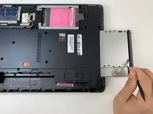
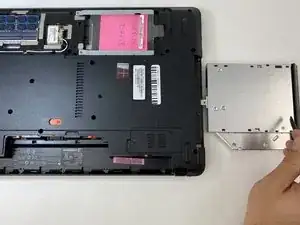
    • Using the flat end of the spudger, slide the optical drive out.

    Do you have an additional intermediate shot showing how this process looks? Also, note that iFixit prefers that you not use arrows, and that the markup you do use relate to the color of the bullets.

    Alex Watkins -

  13. 1k215J4uPSej4CCR
    1k215J4uPSej4CCR
    kEigfvIiT2APCiN3
    GJmSorxcfuKEa1bg
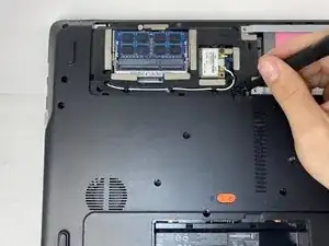
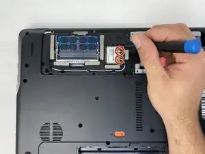
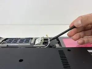
    • Using the hook end of a halberd spudger, gently pry up the black and white wires from the wireless card.

    Where is this component located on the device?

    Alex Watkins -

  14. eQmRiTU2KeMgCQLC
    eQmRiTU2KeMgCQLC
    mr1Ca6LwJbE2GaMQ
    IUMF2Q4ARsJBaWew
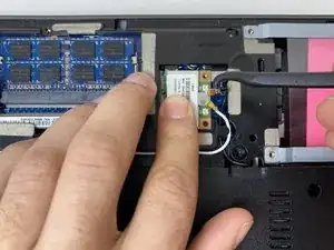
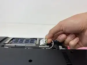
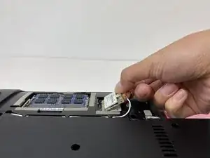
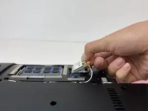
    • Using the flat side of the spudger, pry the wireless card out of its slot.

    • The card will then pop upwards at a 45 degree angle. At this point, gently pull the card out.

    Remove arrow markup. Use bullets that relate to the markup.

    Alex Watkins -

    Also, the pictures don’t seem to show what you’re saying to do. Can you add a flipbook in the middle where it shows the card popped up but before you pull it out?

    Alex Watkins -

  15. mIuvXoSDH5hSRWaH
    mIuvXoSDH5hSRWaH
    UXKW4TccqyCMiQXt
    OYJTUx6DTJgtVj3R
    • Flip the laptop back over.

    • Once the keyboard is removed, use the pointed-end of the spudger to release the touch pad cable.

    • Gently slide both sides of the clip upward towards the screen in order to release the cable.

    Note that since you’re using a black tool on a black component, and you’re zoomed out really far, these pictures do not show the action effectively.

    Alex Watkins -

  16. jU5Iaj2ccF3g1ER1
    jU5Iaj2ccF3g1ER1
    WZGaexN1LSeeBpEe
    2ZobGWZKJWrYjByv
    • Using the spudger, gently slide the clamp holding the MS cable upward towards the screen. Carefully remove the cable from its housing.

    Which method? Make sure to use flipbook style shots, remove arrows everywhere, and match markup to bullets. Past this point, I’m not marking this issue anymore.

    Alex Watkins -

  17. XI2WYYJTmqSEN1tL
    XI2WYYJTmqSEN1tL
    5ACZLppEJMhcIT2I
    MPJxZl4mBWOEOTyk
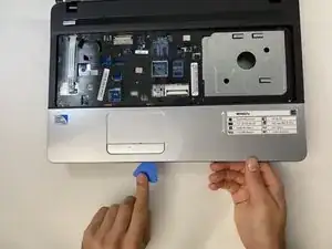
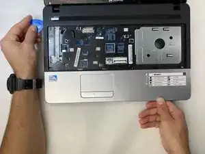
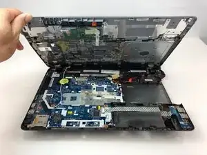
    • Using the opening pick, carefully pry the palm rest assembly upwards.

    • Work the pick around the perimeter until all of the clips are released.

    The orientation changes from the first images to the second and third, which makes this step confusing. I would separate out the first two steps to demonstrate the picks being worked around the perimeter, and then have the lift step separated. Also, note that you used the wrong “your” in the last step.

    Alex Watkins -

  18. JZxfv66dsCVprqOu
    JZxfv66dsCVprqOu
    KfB2FoTdPetAkfSd
    • Gently life the side closest to you up towards the screen.

  19. ngFSTBEDiVxxRDdM
    ngFSTBEDiVxxRDdM
    41BUvrDLZqcMEoOb
    433WLW2dZCwLGrIi
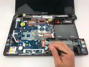
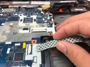
    • Using the plastic spudger, release the cable from the ZIF connectors and remove all four ribbon cables on the motherboard.

    What method?

    Alex Watkins -

  20. PUyscrnwk5tBWCAN
    PUyscrnwk5tBWCAN
    HW5rQqfiuHynbhZg
    3GmaxrvkrZUsoNJ4
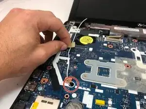
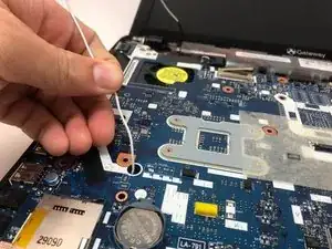
    • Remove the tape holding the white wire and gently pull it out of its hole.

    Instead of referring to the image, indicate what the white wire does. The text and images should function independently.

    Alex Watkins -

    How do you reconnect the cable?

    Tyler Dake -

  21. NIdG3SWq4Ckfa1ls
    NIdG3SWq4Ckfa1ls
    gkJRxE2brLcOGfYH
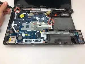
    • Use the Phillips #000 driver to remove the two remaining 3mm silver screws.

    This markup is quite large for the size of the screws. What are the measurements on the screws?

    Alex Watkins -

  22. ktAIC3giAIqPAZ6A
    ktAIC3giAIqPAZ6A
    uneefFrA4OngNjXg
    xyQQVhwVKuUDwbDp
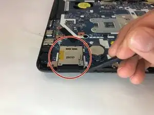
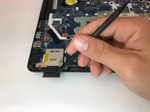
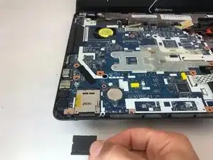
    • Use the spudger to slide the SD card out of the back left corner of the system board.

    Add flipbook style shots here.

    Alex Watkins -

  23. 3BmHwMOMHC4URiGJ
    3BmHwMOMHC4URiGJ
    eYHomAWCKTRpOxGx
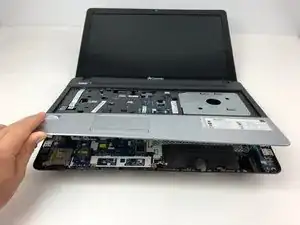
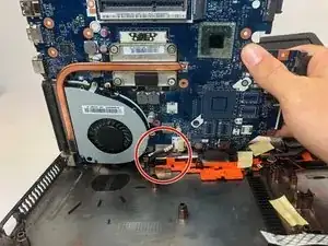
    • Gently lift the motherboard towards the screen.

    • Avoid contact with the connecting cable. Force will cause damage to the cable.

    How can they make sure to not damage the connecting cable? I would change this into direct command and a caution bullet.

    Alex Watkins -

  24. jeLi2ElgoPZtVSF1
    jeLi2ElgoPZtVSF1
    RuaipojlmvL4GL5T
    faExLFlSuYcs3Y1l
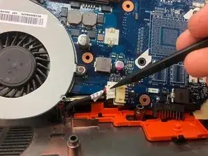
    • Use the spudger to disconnect the last cable holding the motherboard to the system board.

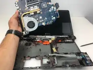
    • Lift the motherboard straight up, being careful not to damage the fan or other sensitive parts.

    How can they disconnect the cable? Note the comma splice in the second step. I would also separate out these into two steps so you can show an image about how to lift the motherboard and how not to damage the parts.

    Alex Watkins -

Abschluss

To reassemble your device, follow these instructions in reverse order.
Piper Moeller

Mitglied seit: 24/01/20

613 Reputation

0 Kommentare