Einleitung

Procedure for dissembling the outer casing of the laptop safely.

  1. S6lEYvUrYwibbAWp
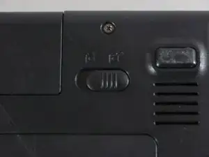
    • Move the latch to the right of the battery to unlock.

  2. KjtYYqwZCqFtLOIo
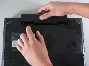
    • Slide the latch on the left directly below the battery to unlock and pull out the battery as shown.

    • The latch must be held in position to remove the battery.

  3. v61G6v6HnVBcAtXS
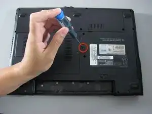
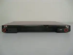
    • Unscrew the marked 5.9 mm Philips screw.

  4. LD3fZrFDuOVTHM4s
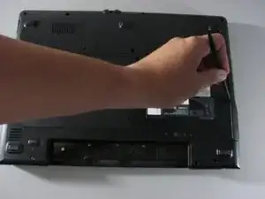
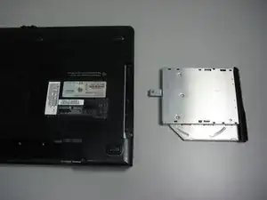
    • Use the spudger to pry out the Disk dive.

  5. pbZPvSPF23KIvdCt
    • The disk drive should easily detach and can now be replaced.

  6. pZZE3i1FTJkSmFmR
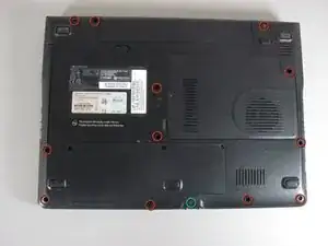
    • Remove the twelve 5.9 mm Philips screws from the back cover.

    • Remove one 8.8 mm Philips screw from the back cover.

  7. Md3nCYvXCI326VDD
    Md3nCYvXCI326VDD
    Tln6IBCiGXMJiSTD
    4gCyYS2XYHdLGtMf
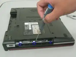
    • Unscrew the two 5.9 mm Philips screws located on the the side closest to the battery.

    • Unscrew the three 3.6 mm Philips screws that are within the Disk drive port.

  8. eofOFfBRHHKyNJNt
    eofOFfBRHHKyNJNt
    qlJiTxBDif56vDNH
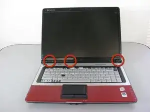
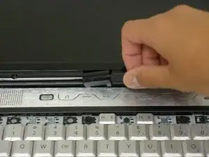
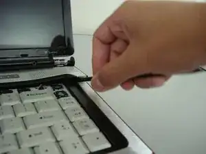
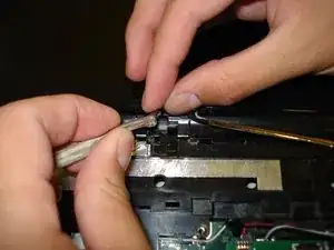
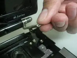
    • Remove the hinge covers by lifting each with the sharp point of the spudger.

    • Notice that the middle cover has a different shape and is more difficult to remove.

    For the middle cover, flip over to the bottom side. You can see the tabs that hold the cover. Slight pressure on these on it pops right off.

    Mark -

  9. obt5tPPpFpdTMEZT
    obt5tPPpFpdTMEZT
    F1JBkq1EUKPIUgPF
    rBuMOL12XUUGqPEm
    • There will be a connection underneath the speaker cover.

    • Remove the speaker cover using the spudger.

  10. VecMuQg1YnPfbVGi
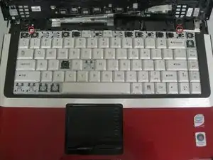
    • Unscrew the two 3.9 mm Philips screws and remove the keyboard.

  11. GFwUUfHmowcwbL65
    GFwUUfHmowcwbL65
    OZ4qppMobt2rb1Uu
    eLKLAKLFjlZGFGTW
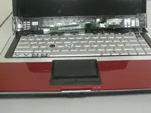
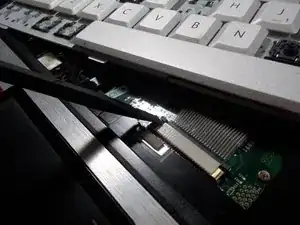
    • Carefully lift the keyboard off from the laptop. It is still attached as shown.

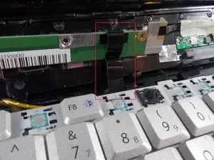
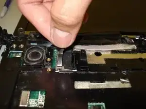
    • Using the spudger, detach the connector by pushing two tabs away from the white connector and then gently pulling the connector away.

    • The brown colored component with the tabs does not come out with the connector.

  12. kPMTvVXyXyGFK6TK
    kPMTvVXyXyGFK6TK
    Qtc3bwNMxmrlefoa
    AsuA3sKPjR4UWKeq
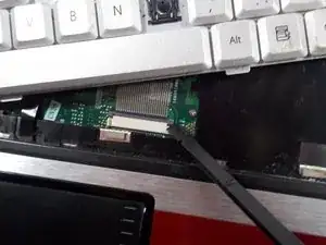
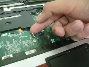
    • Lift up the black tab and gently pull out the connector.

  13. i4OcpRvgySHep44H
    i4OcpRvgySHep44H
    qINC2Bb1GNMCCwWf
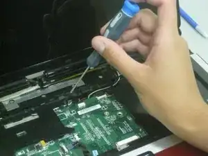
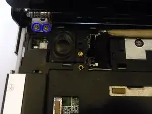
    • Unscrew the four marked 5.9 mm Philips screws.

  14. MgyTVUSTlAJEPGbt
    MgyTVUSTlAJEPGbt
    ptLNfPUTKLDUfrGd
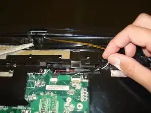
    • Move the wires out of the fixed space as shown.

  15. MXYwUsKaxk6soW2Q
    MXYwUsKaxk6soW2Q
    nu4kDi1Vp1InniV1
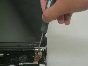
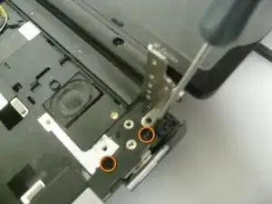
    • Unscrew the five marked 3.8 mm Philips screws.

    • Three screws are located on the right side of the screen.

    • Two screws are located on the left side of the screen.

  16. imA1lLxXxbRNOLW4
    • Remove the screen brackets from the computer's base.

  17. WlIVjeDV6QFxaDMY
    WlIVjeDV6QFxaDMY
    TWRVnJCaRGLERsNK
    1bCIGuu2bfrUjP3g
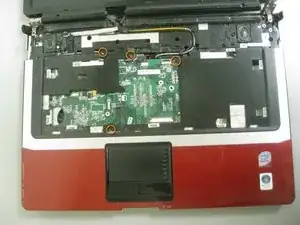
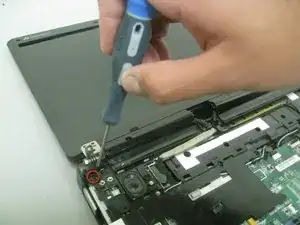
    • Remove the four 5.9 mm Philips screws as indicated:

    • There is one somewhat hidden screw on the left side under the screen hinge, and one to the right of the (left)speaker, right/top side of the video port on mobo.

    • There are two similarly positioned screws on the right side.

    Remove four 5.9 mm Philips scews as indicated:

    There is one somewhat hidden screw on the left side under the screen hinge, and one to the right of the (left)speaker, right/top side of the video port on mobo

    There are two similarly positioned screws on the right side.

    MaxM Tech -

  18. OskPATmTCGycOZyD
    OskPATmTCGycOZyD
    cmtGiZ6isWCn1omh
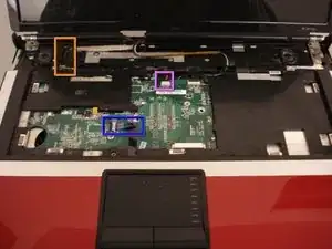
    • The following steps (18 - 20) explain how to remove the three indicated connections.

    • The order is Blue, Violet, Orange.

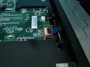
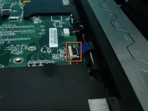
    • Lift the white tab up and gently take out the connector.

  19. YstqhBU5PtSeMyIb
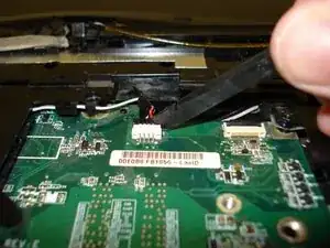
    • Use the spudger to pull off the black attachment.

  20. bSnSHrgyPBJKWh5s
    • Lift and pull the black tab upward until it becomes unattached.

    • Some force may be required.

  21. XDCpFDsZJyBTOp2K
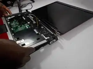
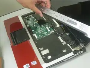
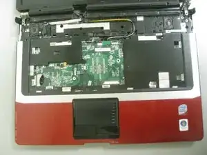
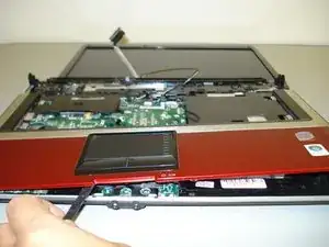
    • Use the spudger to remove the casing as seen in the picture.

    • Some force may be required.

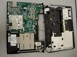
  22. RUJplXn1KSlHUXJc
    • Remove the casing.

Abschluss

To reassemble your device, follow these instructions in reverse order.
Diego Carteno

Mitglied seit: 15/04/10

258 Reputation

0 Kommentare