Einleitung
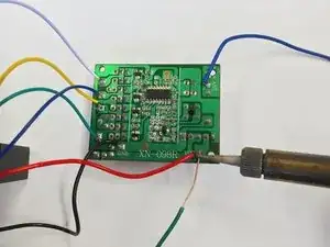
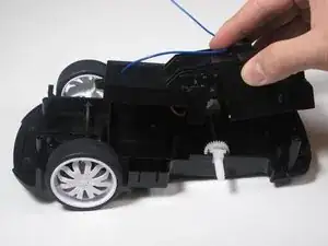
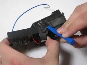
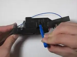
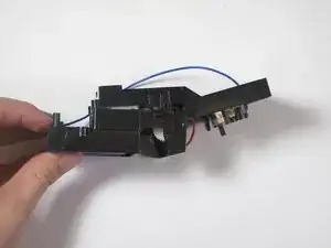
The circuit board of the car delivers information from the remote to the motors so the car can move. If the circuit board has a broken component and no longer works, it's far easier to replace the whole board rather than trying to find the broken component. The following steps will show you how to replace the circuit board of the car.
Note: This guide will involve soldering. For information on how to solder, please visit iFixit's Soldering Skills page.
Werkzeuge
-
-
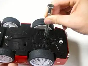
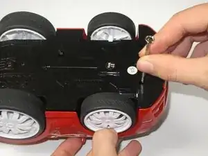
Remove the 5mm Phillips #0 screw from the bottom of the car, located between the rear wheels.
-
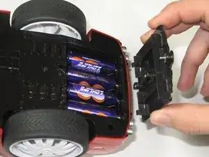
Gently lift the battery cover from the car to expose the batteries.
-
-
-
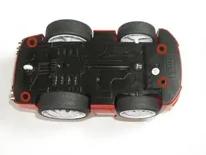
Flip the car over and remove the four 5mm Phillips #0 screws that hold the shell to the car chassis.
-
-
-
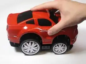
Flip the car over again to its upright position and vertically lift the shell from the car.
-
-
-
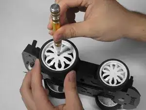
Unscrew and remove the 5mm Phillips #0 screw located at the center of the wheel while holding the wheel still.
-
Slide the wheel off of the axle.
-
Repeat the previous steps for the other rear wheel.
-
-
-
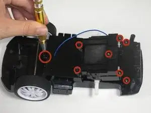
Remove the eight 5mm Phillips #0 screws located on the top of the motor/circuit board enclosure.
-
Vertically lift the motor/circuit board enclosure from the car chassis.
-
-
-
Using a small plastic opening tool, gently pry the clips to release the tabs on the circuit board casing. The clips can be located above where the rear wheels used to be.
-
-
-
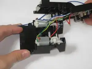
Lift the circuit board casing from the enclosure to reveal the motors, gears, and circuit board.
-
-
-
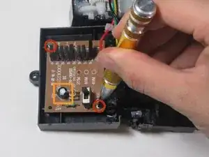
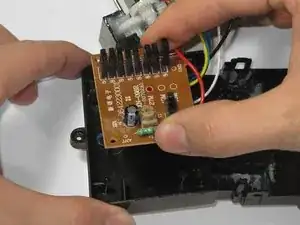
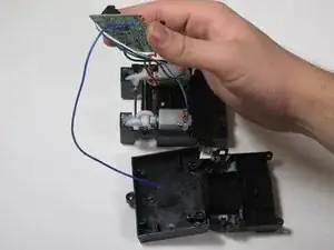
Lift the circuit board from the plastic casing and flip it over to expose its underside where the wires are connected.
-
-
-
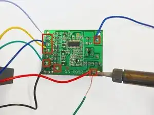
Using the copper solder wick, remove the solder connecting each of the seven wires to the circuit board.
-
To reassemble your device, follow these instructions in reverse order.
Ein Kommentar
From where to buy the board
