Einleitung

Are you having trouble saving all of the cool videos and photos you record? You've tried everything and nothing will work? It may be time to get a new microSD and accessory board so you can enjoy the adventures for years to come!

  1. 4TNtYyuD2xBeQVoD
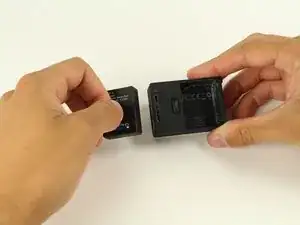
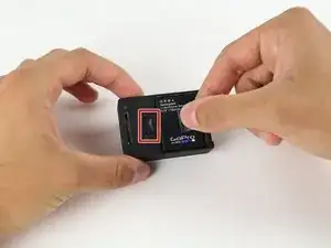
    • Pull the tab on the back of the device to release the back cover. It should come right off.

    • The device pictured does not include the back cover.

  2. SUFhuldYYCJ2OiWU
    • Use the battery tab to pull the battery out of the device.

    • Remove the battery from the slot.

  3. GURuDmbZovAteUVS
    GURuDmbZovAteUVS
    nIoueZ6IvwCYwUFy
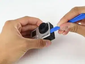
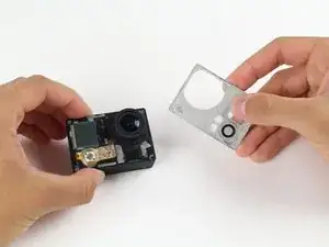
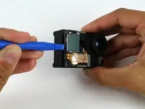
    • Using a plastic opening tool, pry the gray, front face plate until it can be removed from the housing.

    • To avoid breaking or weakening the tabs on the face plate which hold it in place, alternate the sides from which you pry and check each tab before separating the plate from the body.

  4. F2h1ZZlUYakWAuYi
    F2h1ZZlUYakWAuYi
    PiujMCfyxAjVSNNh
    hOqLWK5LdGZyi2KU
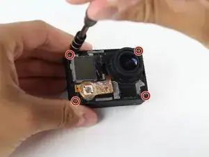
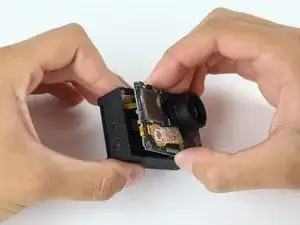
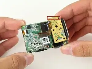
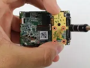
    • Using your screwdriver, remove the four 8.1mm PH00 screws securing the motherboard to the black housing unit and set them aside.

    • Use the plastic opening tool to help pry the motherboard/midframe up from the main housing. Once you can get a hold of the edge, simply pull the internal components up and out!

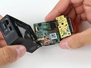
    • Watch out for the ribbon cable connecting the midframe and the motherboard to the GoPro housing. See the next step.

  5. liJBYPPY2KytGJHI
    liJBYPPY2KytGJHI
    joH3QTGU6BVYZQJt
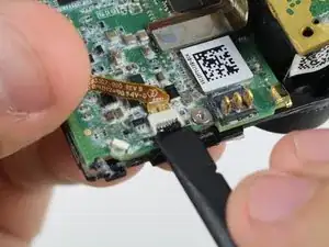
    • Remove the ribbon cable connecting the housing to the motherboard by flicking up the black clip with the spudger tool and gently pulling the cable out.

  6. TH3bsHuUdnFPnV1m
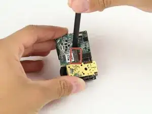
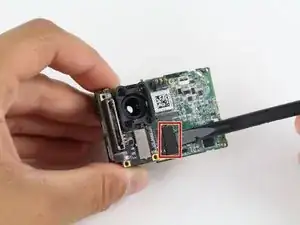
    • Once the internal components are removed, take out your handy dandy spudger tool and pry off the piece of tape that holds down the image sensor.

    • Disclaimer: Our device is just a teardown unit and no longer has the tape. The markup depicts the location where the tape would be located.

  7. auZETY1SmDBrHrJN
    • Using your screwdriver, remove the four PH00 screws securing the image sensor to the motherboard.

    • Disclaimer: The unit used for this guide did not include these screws. Set them aside so you do not mix them up with the previously removed screws.

    Removing this and attempting to reconnect the connector ribbon will be really difficult when re-assembling. If you are simply replacing the LCD screen I recommend skipping to Step 13.

    Devin Roach -

  8. CAmohBdao2q1K1RJ
    CAmohBdao2q1K1RJ
    l6TBivaMpc1Dwce1
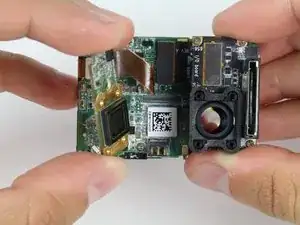
    • Using the spudger tool, pry off the connector ribbon from the motherboard (don't worry it comes off pretty easily).

    • Remove the image sensor from the motherboard assembly.

  9. LgPq2pmFvG1gDFPb
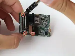
    • Using your screwdriver, remove the three 4mm PH00 screws that hold down the metal plate.

    The threads on the top left screw are different so be sure to take note of which screw is which (although maybe it doesn’t matter that much).

    Devin Roach -

  10. WKwMZIdNK1GjC6Tm
    WKwMZIdNK1GjC6Tm
    WMZQgDJrWmeVn4VT
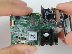
    • Using the spudger tool, pry off the corresponding ribbon cable from the motherboard.

    • The microSD/accessory board is ready to come off.

Abschluss

To reassemble your device, follow these instructions in reverse order.

Kyle Rooney

Mitglied seit: 14/04/15

502 Reputation

Ein Kommentar

I bought a replacement from iFixit. I follow the guide, but it still shows same error “No SD”. Any advice?
Daniel Nielsen -