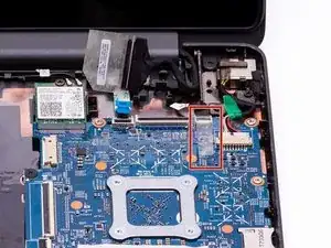
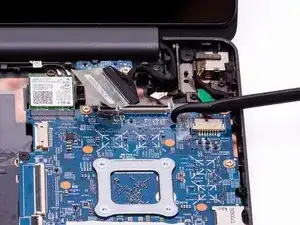
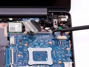
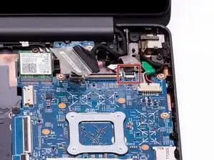
Einleitung
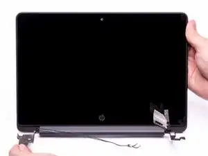
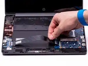
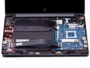
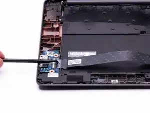
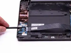
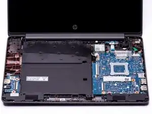
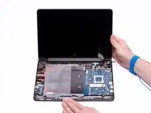
The Touch Display Replacement Guide provides the steps required to remove the HP Chromebook’s Touch Display. The touch display may need to be replaced if the display no longer responds to the user’s touch, the screen won’t illuminate with the power on, or the screen becomes broken or cracked. Prior to replacing the touch display, ensure all of the troubleshooting steps have been completed in accordance with the Troubleshooting Guide. If the display must be replaced, the complete touch display assembly has to be replaced due to the touch functions.
Removing the keyboard will expose the internal components of the computer. These components are electrostatic discharge (ESD) sensitive components. It is important to ensure that an anti-static wrist strap and anti-static mat are used to prevent ESD from damaging other components inside of the device. For proper use of the anti-static wrist strap, refer to iFixit’s “How to set up your Anti-static mat and wristband” Guide.
Werkzeuge
-
-
Disconnect the power adapter from the charging port and remove all external media devices from the Chromebook.
-
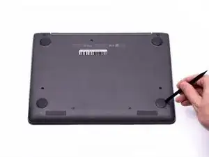
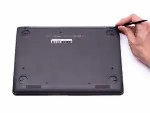
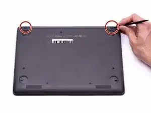
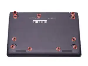
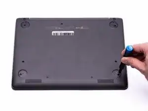
Turn the Chromebook over so the bottom of the computer is facing upwards with the hinge facing away.
-
-
-
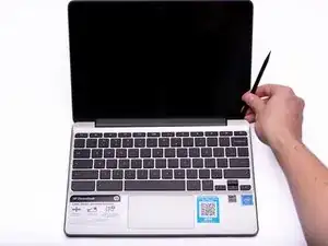
Place the Chromebook upright and open the screen all the way.
-
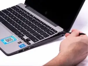
Starting towards the hinge, insert the spudger between the silver keyboard decking and the charcoal colored casing.
-
Pry upwards to release the tabs that are securing the keyboard to the casing.
-
Repeat this process around the perimeter of the keyboard to ensure all tabs are released.
-
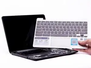
Once all the tabs are released, gently lift the keyboard to gain access to the (2) Zero Insertion Force (ZIF) ribbon cables.
-
-
-
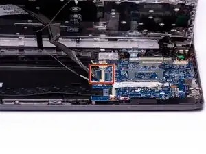
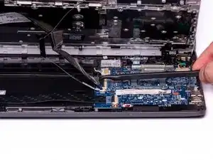
Using the hook on the Halberd Spudger, lift up the ZIF connector tab for the keyboard ribbon cable. They keyboard ribbon cable is the larger of the two ribbon cables.
-
-
-
With the ZIF connector tab in the upright position, use your fingers to gently pull the keyboard ribbon cable out of the ZIF connector.
-
-
-
With the hook on the Halberd Spudger, lift the ZIF connector that is holding the Touchpad ribbon cable. The Touchpad ribbon cable is the smaller of the two ribbon cables.
-
-
-
With the ZIF connector tab in the upright position, use your fingers to gently pull the Touchpad ribbon cable out of the ZIF connector.
-
-
-
With both ribbon cables disconnected, the keyboard can now be safely removed from the Chromebook.
-
-
-
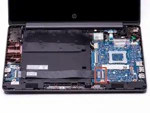
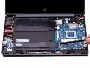
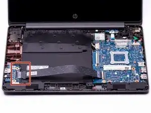
Using the hook on the halberd spudger, lift the external media board ZIF connector attached to the motherboard.
-
-
-
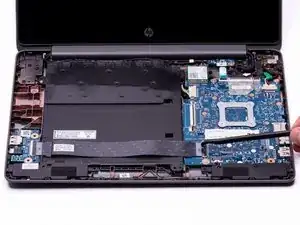
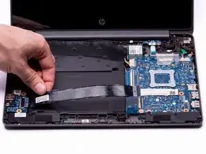
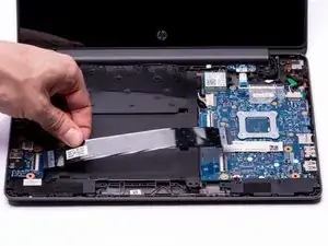
With the external media board ZIF connector lifted, using your fingers, gently remove the media cable from the motherboard.
-
-
-
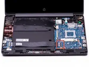
Using the hook on the halberd spudger lift the ZIF connector on the External Media Board.
-
-
-
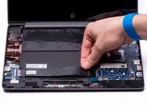
With the ZIF connector in the upright position, use your fingers to gently remove the media cable completely from the computer assembly.
-
-
-
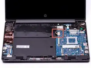
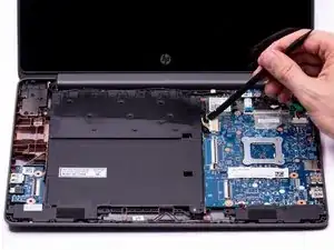
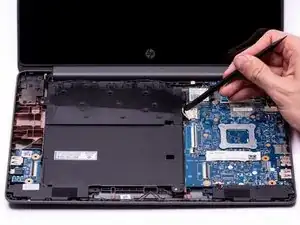
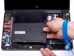
Use either end of the spudger to remove the battery bundled cable connector from the motherboard.
-
-
-
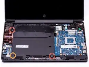
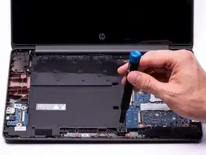
Using a Phillips #00 Screwdriver, remove the two silver 3.4 mm screws from the battery.
-
Using a Phillips #00 Screwdriver, remove the black 4.8 mm screw from the battery. This screw also secures the left speaker to the casing.
-
-
-
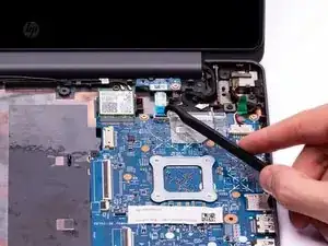
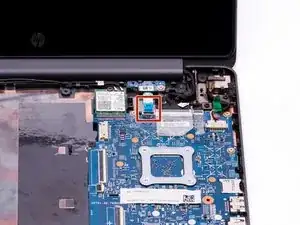
Using the hook on the halberd spudger, gently lift up the ZIF connector tab that connects the Hall Sensor Board ribbon cable to the Motherboard.
-
-
-
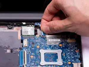
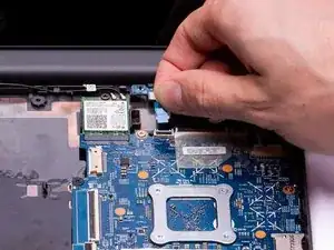
With the ZIF connector tab in the upright position, gently pinch the blue lifting tab and remove the Hall Sensor ribbon cable from the ZIF connector.
-
-
-
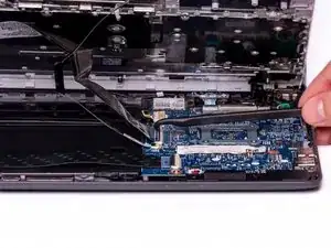
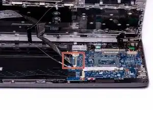
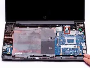
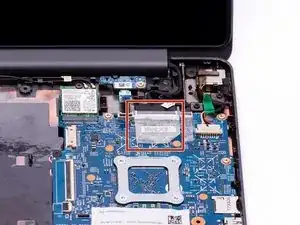
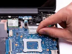
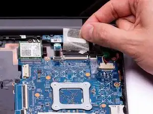
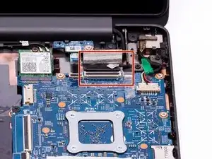
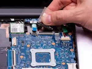
Using your fingers or the hook on the halberd spudger, gently lift up the clear plastic sticker to reveal the ZIF connector securing the LVDS Touch Display to the Motherboard.
-
-
-
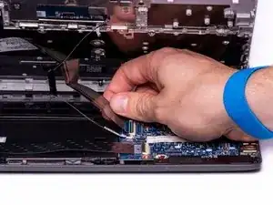
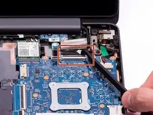
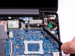
Using the hook on the halberd spudger, gently lift the ZIF connector tab securing the Touch Display LVDS cable to the Motherboard.
-
-
-
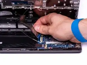
With the ZIF connector tab in the upright position, gently remove the Touch Display LVDS cable from the ZIF connector.
-
-
-
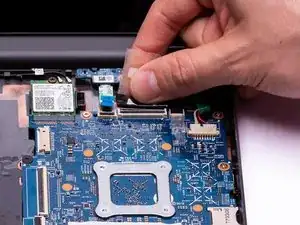
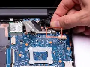
Using your fingers or the hook on the halberd spudger, gently lift up on the plastic sticker to reveal the Webcam ZIF connector.
-
-
-
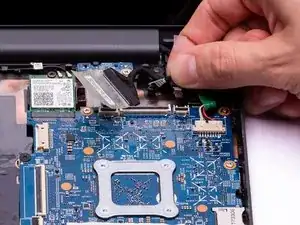
With the Webcam ZIF connector tab in the upright position, gently pinch the black lifting tab and remove the connector from the ZIF connector on the motherboard.
-
-
-
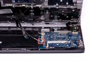
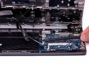
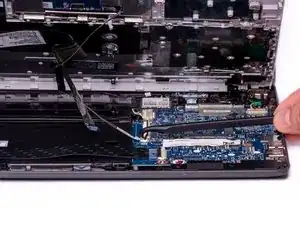
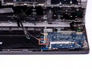
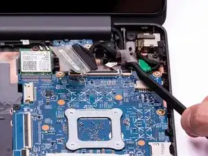
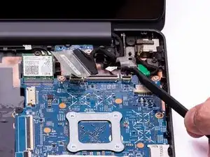
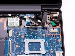
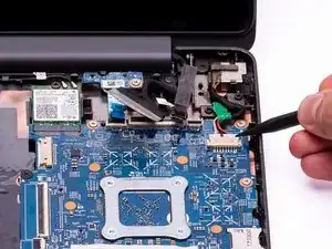
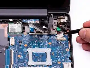
With either end of the spudger, remove the charging port cable from the bundle connector on the motherboard.
-
-
-
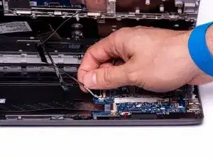
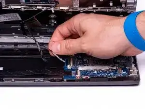
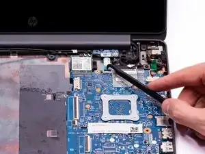
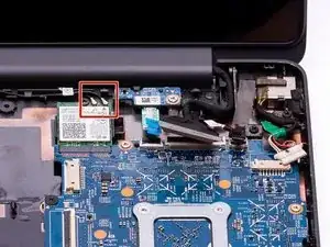
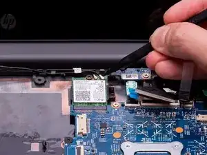
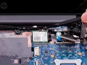
Using the fine point of the spudger, gently lift up the (2) antenna coaxial connectors on the WLAN module.
-
-
-
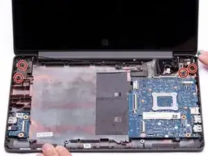
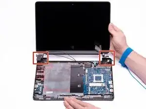
Using the Phillips #00 Screwdriver, remove the (4) 4.6mm screws from the left and right mounting brackets.
-
-
-
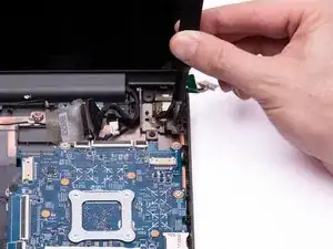
With one hand holding the base of the Chromebook, use the other hand to lift the display away from the base.
-
To reassemble your device, follow these instructions in reverse order.
