Einleitung

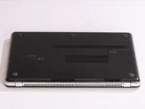
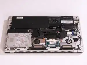
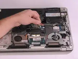
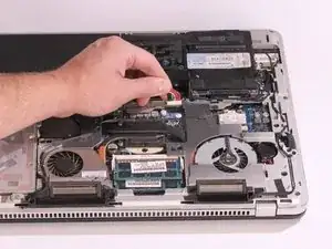
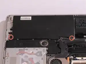
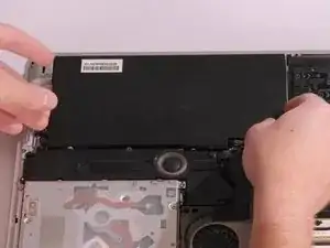
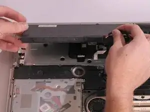
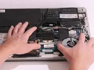
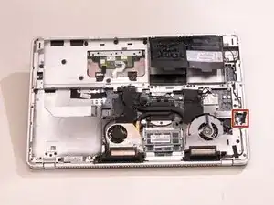
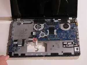
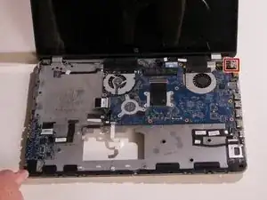
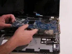
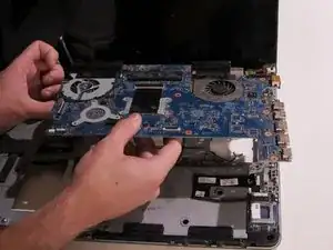
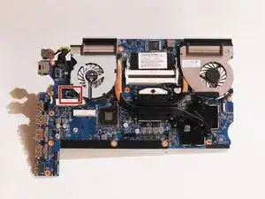
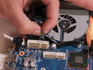
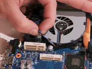
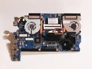
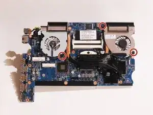
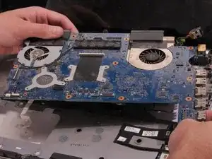
Follow this guide if you want to replace the motherboard of your HP Envy 17-3070NR. The motherboard connects all parts of the PC together and it is a most complex part of the computer. Unfortunately, with great complexity comes great room for failure. Should any of the components on the motherboard fail, whole motherboard needs to be replaced to fix the issue.

  1. QsKnyogwUQGXdFyg
    QsKnyogwUQGXdFyg
    dPwl4kaZAZU4De4v
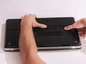
    • Before you begin taking apart the computer, make sure that it is completely powered off.

    • Slide the release latch away from the nearest edge.

    • Slide the back cover off of the computer.

  2. gQSHeYHLaYFvUdQv
    gQSHeYHLaYFvUdQv
    RENSYWZJDLAURVpG
    k5OB56NDZhjJNcBV
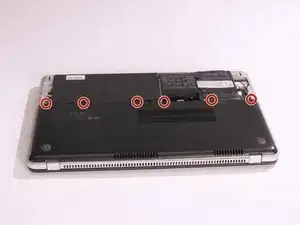
    • Remove the six 3.7mm Phillips screws.

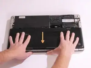
    • Slide the back cover until it clicks, then lift it straight off.

  3. F3nHwB1KJ2ieBAeS
    F3nHwB1KJ2ieBAeS
    nfZlSIjHuZ5eHLPY
    lPViGNB1SHRY1GZv
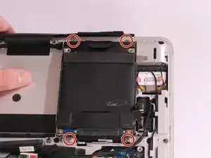
    • Remove the four 3.7mm Phillips screws that hold the hard drive onto the computer.

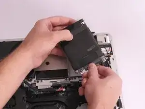
    • Remove the hard drive by lifting it out of its cavity.

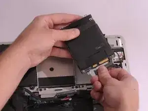
    • Unplug the hard drive cable that connects it to the main assembly.

  4. oZTvcuvbLMNCI5G6
    oZTvcuvbLMNCI5G6
    SwS4HR1EbsDhdfRr
    • Disconnect the multi-colored battery cable from the main assembly by gently pulling upward on it.

  5. rAKUbeZleahSNJhW
    rAKUbeZleahSNJhW
    NEsdLTAXPEDIkTi6
    PmHbSePQKgA4nqtN
    • Remove the two 3.8 mm Torx screws using M8 Torx screwdriver.

    • Remove the battery by pulling it straight out away from the computer.

    • It is much easier to use the battery cable to carefully lift the battery off than to try to pry it off with tools.

    Has anyone found a place that sources replacement batteries for these? As far as I can gather HP is not supplying this model's battery nor have I been able to source any equivalent after market battery. Looking on forums it seems others have the same problem!

    cejay -

  6. HatdHX1lGu6iNIqO
    HatdHX1lGu6iNIqO
    Yllj3aqicggsyNJq
    DLmJaRitjEqKWBju
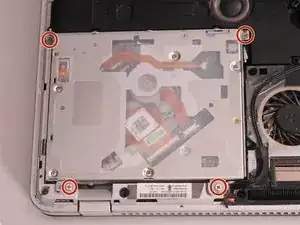
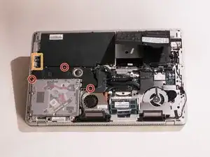
    • Remove the four 3.7mm Phillips screws that secure the optical drive to the computer.

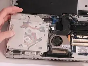
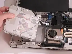
    • Slowly lift the optical drive away from the computer ensuring that you don't put stress on the connecting cable.

    • Do not fully lift off the optical drive as there is still a cable that connects it to the motherboard.

    • Remove Sub Speaker assembly first in order to remove Optical drive. Carefully disconnect speaker connector.

  7. EkbnoiruyeBmJKY2
    EkbnoiruyeBmJKY2
    jvsXNHtuJjLaVUpi
    B2xwUFfCeSPSTKRc
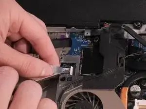
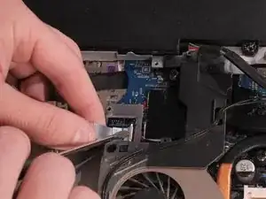
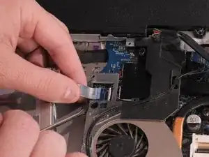
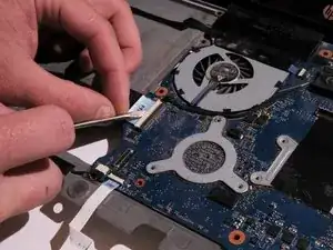
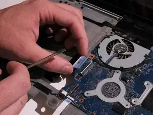
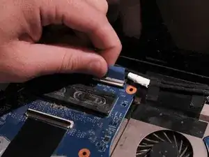
    • Carefully disconnect the connecting cable by lifting the white clamp with a Flathead screwdriver and pulling on the blue tab away from connector.

  8. gTmJGeZAarFk4JEN
    gTmJGeZAarFk4JEN
    ydILYCS4MQSYPwXj
    gQnLYdDrM1bmCAq3
    • Unscrew the three 6.5mm Phillips shoulder screws that connect the subwoofer to the computer.

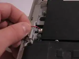
    • Disconnect the red and black subwoofer cable from the system board by pulling it upwards.

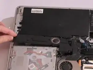
    • Remove the subwoofer by pulling straight up from the main assembly.

  9. wp3KPDfQkDjuGsbN
    wp3KPDfQkDjuGsbN
    4EZ2A6Qq4YdpYiEW
    lOMhmyvpmQfmXRGr
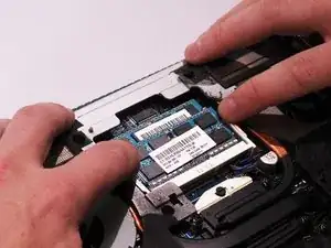
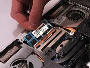
    • Press down on both tabs on either side of the top RAM stick.

    • The RAM will slightly pop out and you will be able to slide it out of it's cavity.

    • Repeat the same process for the second stick of RAM if needed.

  10. u3BHorwEQ33akMZR
    u3BHorwEQ33akMZR
    2TugGeEsYWOs6IYY
    2nZEtbASkfgymrkJ
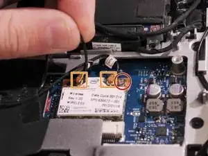
    • Unscrew 4.5mm Phillips screw.

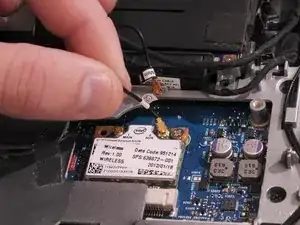
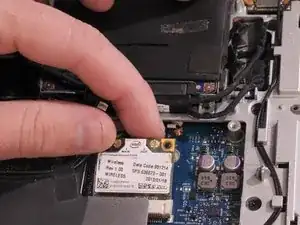
    • Unplug both antenna connectors by carefully pulling them upwards.

    • During re-assembly make sure to match numbers(1 or 2) on the antenna cable and the wireless card.

  11. JDBsLENUvhMeowkw
    JDBsLENUvhMeowkw
    lGQJOGO5JbsZFZy6
    QTSkPQPIZhxnTXB6
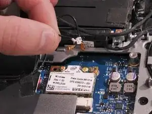
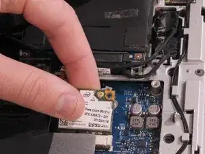
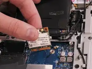
    • Pull wireless card up and away from you.

  12. dQGA2XXwCcxSRlVm
    dQGA2XXwCcxSRlVm
    OVFGK4QUf5ft5PXs
    KQO3M6HPmWAFnuFB
    • Unplug CMOS battery by gently pulling upwards on it's cable.

  13. yoURJjRiJEl2LLoj
    yoURJjRiJEl2LLoj
    tlx2oeICCRyVYLgB
    2AEVaYeEVNXwGia1
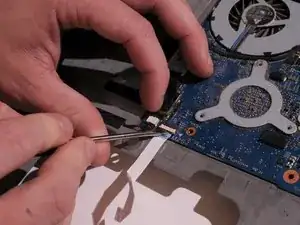
    • Remove the first connector by lifting the white clamp with a Flathead screwdriver and pulling the connector to your right.

  14. trGUNpQVPRyiFYyH
    trGUNpQVPRyiFYyH
    iAIONmbwLYSGRoAD
    RxaL146mFy6FGOWZ
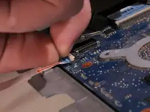
    • Remove the second connector by gently pulling upward.

  15. r3XiUySmRBvZSPHI
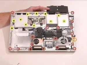
    • Remove the seventeen 6.6mm Phillips screws.

    • Remove the three 3.6 mm Phillips screws.

    • Remove the eleven 3.2mm Phillips screws

    • Three of the 3.2mm Phillips screws are located underneath the black hard drive flap.

    • Make sure that you keep the screws organized so that you keep track of all of the different sizes and locations.

  16. PZSFqiRPNX4wIINK
    PZSFqiRPNX4wIINK
    QjsREXfc1EsVnoCC
    ENJla1uiOaoNcpaH
    • Flip the laptop over.

    • Use a Plastic Opening tool to carefully pry all around the top cover up off of the remaining assembly.

    • Starting location for prying does not matter as long as you pry all around the frame before lifting it off.

    • Do not fully lift the top cover because there are cables that will need to be disconnected before removal.

  17. JLgG2YUOMo4JWovy
    JLgG2YUOMo4JWovy
    gOMdA6JWEhQXbYMV
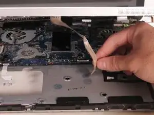
    • Gently pull the white connector shown in the picture towards you to disconnect it from the system board.

  18. I2AI26midvQmcV6r
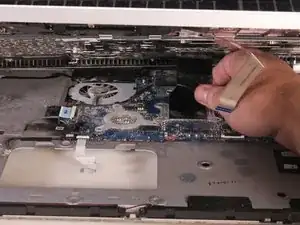
    • Gently pull the black connector towards you to disconnect the top cover from the main assembly.

    • Once both connectors are disconnected, lift the top cover off of the main assembly.

  19. VE5LvxLevbTXnNLK
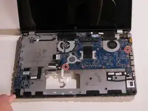
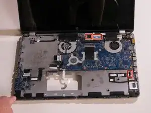
    • Remove the two 4.5mm Phillips screws from the system board

  20. lNcXxylrGRWoquGk
    lNcXxylrGRWoquGk
    OH4LyiViDeDReS2R
    S4eybqtOY6pKHc1Y
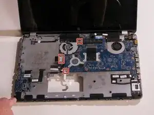
    • Disconnect three cables by lifting a white clamp with a Flathead screwdriver and pulling on the blue tab.

  21. CoLY5OLMSDpu3O4M
    CoLY5OLMSDpu3O4M
    KntgZCwULJv3T6Up
    Wk2UGBkegWsvs1b1
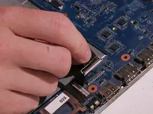
    • Disconnect three cables by pulling upward on black or blue tabs connected to them.

  22. fZAHgaBVBciB1OVN
    fZAHgaBVBciB1OVN
    WBSDMT1RMLOCaJiP
    PXgkiavjFvHoTHIv
    • Disconnect cable by using a Flathead screwdriver to gently pry it off the black connector towards you.

  23. SpDQjSsKZyL5TUb3
    SpDQjSsKZyL5TUb3
    AtR56P2nBODqpG2s
    Usl1Iv63d1mD1vDL
    • Lift up the power connector from the clip.

  24. V2Zl33xqXDaGZrpy
    V2Zl33xqXDaGZrpy
    oYqCQUMqd3Ycq6Sh
    wvNHXji542h5eRKn
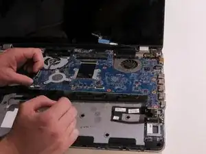
    • Carefully lift up motherboard from the main assembly.

  25. 3MO1PGdZKbAm4C5K
    3MO1PGdZKbAm4C5K
    EXiXGplhXcGGUUZS
    qMEvgobtP55mbcQX
    • Flip the system board over.

    • Unplug the first fan assembly cable by carefully pulling it upwards.

  26. jIpqXHRADGGS6CXC
    jIpqXHRADGGS6CXC
    TWODoJDAuLuZXYR2
    CZD1aDbZIpxnCBmZ
    • Unplug the second fan assembly cable by carefully pulling it upwards.

  27. scas53FCyavLtlrs
    scas53FCyavLtlrs
    6PCwwYWdAksGVoSi
    KqGAQgJsXXGfefXd
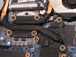
    • Remove the three 4.5mm Phillips screws on the fan assembly.

    • Loosen the seven captive Phillips screws in the ascending numerical order (1-7). Numbers are printed next to each screw on the housing.

    • Screws will not fully come off the assembly. You need to only loosen them.

    • Remove the fan assembly from the system board by lifting it straight up.

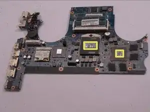
    • For reassembly, you will need to clean the old thermal paste off of areas highlighted in yellow as well as matching parts on the fan assembly. Following that, you would need to reapply thermal paste before putting back the fan assembly. Small amount of the size of the rice grain should be enough for each plate.

  28. mNBPFpTduoywleAm
    mNBPFpTduoywleAm
    Fp1hIsIDmpE21KVj
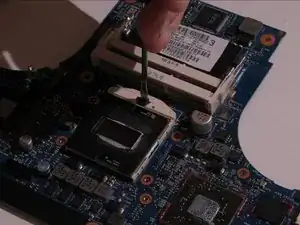
    • Unlock CPU by turning the locking screw 180 degrees counterclockwise using Flathead screwdriver. You will hear a slight click when CPU is fully unlocked.

    • Carefully lift CPU upwards by holding it from both sides.

    • It is important to lift CPU straight upward in order to not bend any pins on it.

    • For reassembly, make sure to put CPU back by matching a small yellow triangle in the corner of CPU to the small triangle imprinted on the CPU socket.

  29. lPUfFaB6LuhGIhvp
    lPUfFaB6LuhGIhvp
    FyE4isR23b1XtOZP
    YBZOfWQaHKMcEvMl
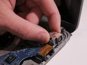
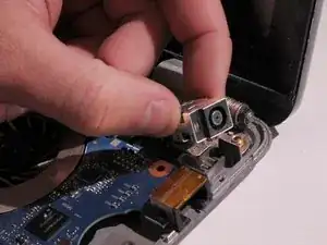
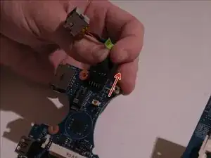
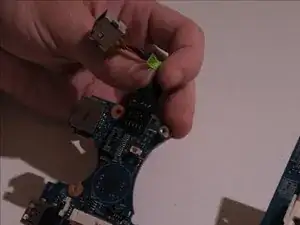
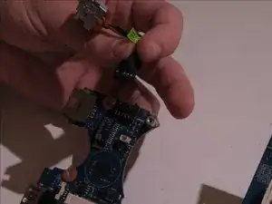
    • Detach the power connector by pulling it away from the motherboard.

Abschluss

To reassemble your device, follow these instructions in reverse order.
Jasper Lewin

Mitglied seit: 21/04/15

748 Reputation

0 Kommentare