Einleitung

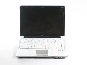
Before replacing your keyboard, remove the battery. To remove the keyboard you will first remove some covers on the back of your computer, the optical drive, and the keyboard frame.

  1. 1WiL4KvHvVUlNKbr
    • Turn off your laptop and disconnect the power adapter before doing anything else with your computer.

  2. fVcNkVVDod1b2IUn
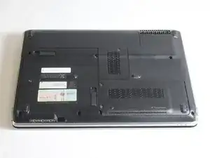
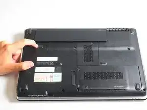
    • Turn your laptop over so the bottom of your laptop is facing up and the hinge is located away from you

  3. M1TMMvOqqftpNxi2
    M1TMMvOqqftpNxi2
    fGNNWRtlgKYCGqHZ
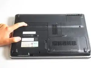
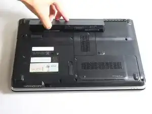
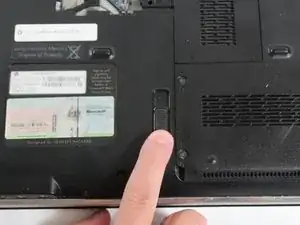
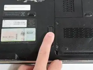
    • Slide the lock switch to the left.

    • The lock switch is located by the bottom left side of the battery.

    • The battery should pop up after you move the switch.

  4. x6wBvoBLMEyp6W4C
    x6wBvoBLMEyp6W4C
    EoD2H4m2aaMrvboG
    q6lVEwidN3ON1Rqa
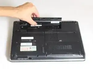
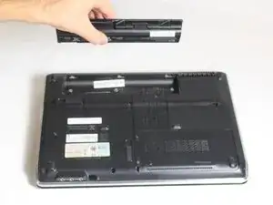
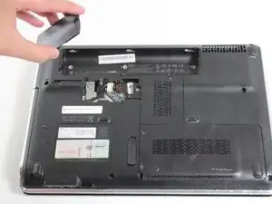
    • Lift up the released battery by rotating it up and away from you.

    • Pull the battery out.

    • The battery is held in by a latch in the front of the battery socket and by tabs in the back. When putting the battery back in, line the tabs back up with the grooves located in the back of the socket and rotate the battery towards you. When in place, push the battery in until you hear a click.

  5. hJRkGPGFoBxyMYm1
    hJRkGPGFoBxyMYm1
    Oq2gsl2RBkLTYBQF
    jKpuM2GyrL6vpniV
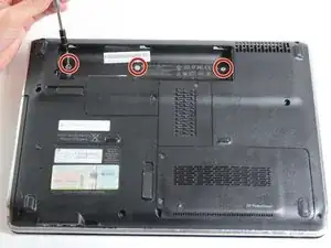
    • Turn the laptop over so the bottom is facing up and the hinges are pointed away from you.

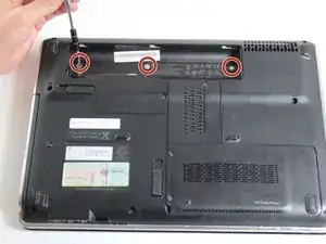
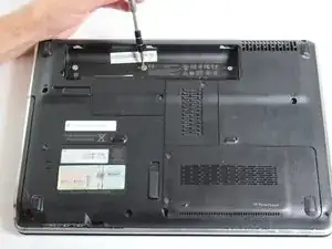
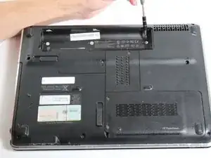
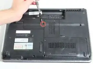
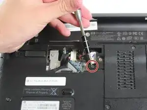
    • Use a Phillips #0 screwdriver to remove the three 2.5 mm screws that are located in the battery socket.

    • The screw sockets are marked by a triangle pointing at each screw socket.

  6. vCcIJfoTALGEZRHn
    vCcIJfoTALGEZRHn
    ITrukYCt1qj2JxEo
    4D516bfF1MUWoiAQ
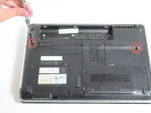
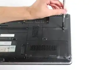
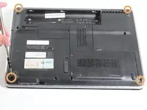
    • There are 6 screws on the back of the computer - two 14.5 mm screws and four 7.5 mm screws.

    • Remove the two 14.5 mm screws with a Phillips #0 screwdriver.

    • The 14.5 mm screws are marked by a small keyboard symbol adjacent to the screws.

    • Remove the four 7.5 mm corner screws with a Phillips #0 screwdriver.

  7. mxalPZIMV2aYrFBP
    mxalPZIMV2aYrFBP
    KaoHVs5Hdxf21Bhg
    xKJbKNbCZAkCHJIQ
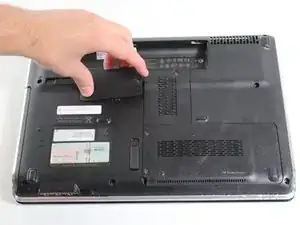
    • Locate and unscrew the 7.5 mm screw on the CMOS cover.

    • Pull up the cover with your fingers.

    • Remove the cover.

    • You may have difficulty removing the cover, if so use a spudger to remove the cover.

    • The screw in the CMOS cover cannot be removed, it will remain with the CMOS cover. The screw is used to tighten and loosen the cover.

  8. bwxXWyBoEkI5CidA
    • Use a Phillips #0 screwdriver to remove the 14.5 mm screw that is located inside the CMOS socket.

    • This screw is labeled with a small picture of a keyboard adjacent to the screw.

    • Many different kinds of screws are removed in this process. Make sure you do not mix them up.

  9. FPBQeGGpuIPeNMlT
    FPBQeGGpuIPeNMlT
    gJZR6iZsAEduGK4Y
    • If the lock switch is operational, slide the lock switch up vertically to release the optical drive.

    • This step is for removing the whole optical drive and not the optical drive control panel. Both steps will lead to unscrewing the optical drive screws.

    • Remove the optical drive after it is released.

    • Step 10 will go over the steps to take if your lock switch is not operational. Skip step 10 if you were able to eject the optical drive with the operational optical drive lock switch.

  10. D46OScoLyZBawvJn
    D46OScoLyZBawvJn
    ibyj5cqmlMCvfEG6
    fjZOxcPZDQShgLek
    • This step is used only if your optical drive lock switch is not operational or broken.

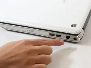
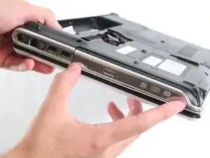
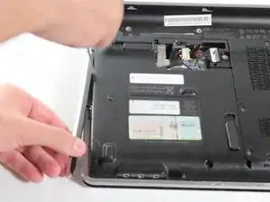
    • Locate the optical drive on the bottom left wall of the laptop.

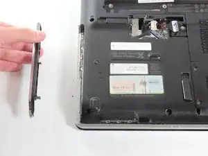
    • Remove the optical drive control panel with a thin flat tool

    • If your optical drive lock switch is operational, then use the lock switch instead to eject and remove the whole optical drive as explained in step 5. It is easier to use the lock switch to remove the whole optical drive.

  11. 4Wtc3pCK3UJaDrWT
    4Wtc3pCK3UJaDrWT
    IJCrFLDSiVpW4PJk
    FhYcJV4eLCqPCIS4
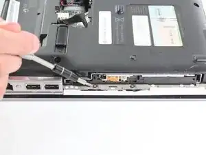
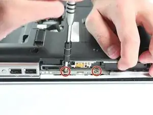
    • Remove the two 2.5mm screws with a Phillips #0 screwdriver.

  12. VOcrCMh6vxFqEIWi
    VOcrCMh6vxFqEIWi
    2aBHZOqUNqhFwYcE
    i2gAxVerVXhEVCcl
    • Turn the laptop over and open the laptop.

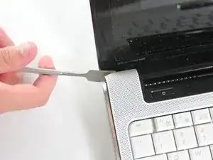
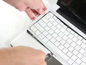
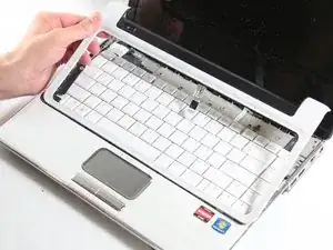
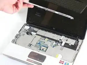
    • Do not pull the frame all the way up because there are two flat cables located beneath the frame that could tear if pulled too hard.

    • Gently lift up the frame surrounding the keyboard without pulling off the keyboard.

    • Use a plastic opening tool or opening picks to lift the frame. Metal tools should be used as a last resort, as they may cause further damage to the device.

  13. bY5j4RCNA1MTWwqA
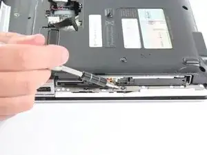
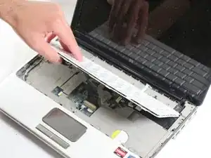
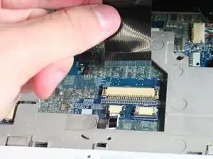
    • Disconnect the 2 ribbon cables attached to the surrounding keyboard frame.

    • Do not pull up the keyboard with the surrounding keyboard frame.

    • Remove the surrounding keyboard frame but not the actual keyboard.

  14. DGacfOs3orXPp1Gy
    • Underneath the keyboard there is a flat cable that connects the keyboard to the computer. Do not remove the whole keyboard just yet because there is a cable that has to be detached first. If the keyboard is pulled too hard, the cable may rip.

    • Gently lift up the key board from the side closest to you, flipping the keyboard away from you. Do not remove the whole keyboard just yet because there is a cable that has to be

  15. sZDqWaCiRXTivnG5
    sZDqWaCiRXTivnG5
    yCAkGFEBTEem16wM
    Gs3SJoOWgYq3KFGF
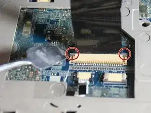
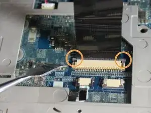
    • Locate the two grey tabs on the right and left sides of the ribbon cable.

    • Push both grey tabs up towards the back side of the laptop with your fingers or a plastic spudger.

    • The metal spudger is great when you need serious prying power, but it is not ESD safe, and may cause further damage to your device. The regular black nylon spudger or a plastic opening tool should be used whenever possible.

    • When the two gray tabs are pulled up, you are ready to go on to the next step.

  16. 4iUFixobESepLmxf
    4iUFixobESepLmxf
    tvHmkoYGOl2gLKIQ
    • Gently pull the flat cable out of the retaining flap with your hands.

    • The flat cable is very weak so be careful when handling it.

    • Remove the keyboard from the laptop.

    • When replacing the keyboard frame, make sure to reattach the 2 ribbon cables and then insert the bottom keyboard tabs into the grooves.

    • Insert the keyboard after the keyboard frame is in place by attaching the tabs into the grooves and pushing the keyboard into place.

    what is the part number

    oskar1mx71 -

Abschluss

To reassemble your device, follow these instructions in reverse order.

Megan Todd

Mitglied seit: 23/09/15

600 Reputation

3 Kommentare

On Step 13, there is a screw connecting the frame near where your left hand is gripping the frame that was not mentioned. You have to lift the keyboard a bit to access it.

Mike Hoover -

Edit to my earlier comment: On Step 13, there are two screws connecting the frame near where your left hand is gripping the frame that were not mentioned, one similar in size to the two that were removed after the optical drive in step 11 and one similar to the four removed in step 6. You have to lift the keyboard a bit to access them.

Mike Hoover -

Great Guide!!
Mike Hoover -