Einleitung

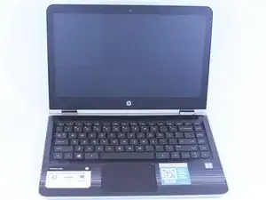
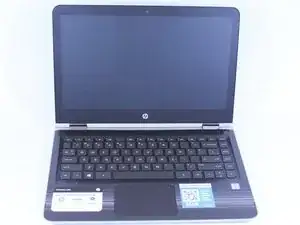
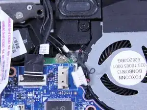
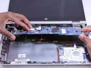
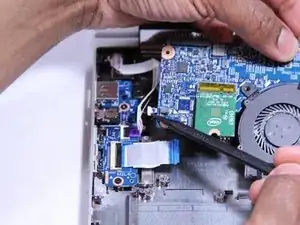
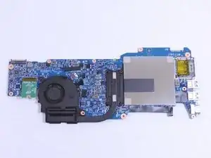
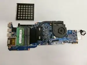
In this guide we will be showing you how to replace the RAM on your HP Pavilion x360 m3-u103dx. This will help if your computer starts to slow down or if you are just looking for an upgrade. The RAM is located on the underside of the motherboard when coming from a keyboard first entry.

  1. gYjHTcKfxLLAZLso
    • Shut down the computer.

    • Disconnect the power and all external devices connected to the computer.

    • Working on your device while it is turned on may result in electric shock.

  2. SovjkqN66AjVjmjq
    SovjkqN66AjVjmjq
    ikon1NpYoVFHUbxW
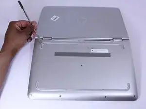
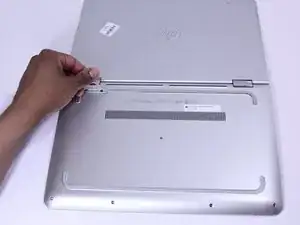
    • Use a Metal Spudger and remove the rubber foot closet from the bottom of the laptop.

  3. xO2oIVxVihIMUncV
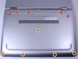
    • Remove all of the screws located on the bottom of the laptop:

    • 5 Phillips 2.4 x 5.7 mm screws

    • 5 Phillips 2.0 x 5.0 mm screws

    • Make special note of each screw and screw lock size and location during removal and replacement.

    “5 Phillips 2.4 x 5.7 mm screws”

    “5 Phillips 2.0 x 5.0 mm screws”

    I think the color for the sizes are mixed up, because the one near the screen bending part are the bigger ones, yet it says they are the “2.0 x 5.0 mm” but they are the bigger ones.

    If I’m wrong, tell me because I’m not sure if thats the ways they’re named because I’m not an expert at screw sizes.

    SomeRandomChild -

  4. Ol3BWZHvYObRMjw3
    • Turn the computer over onto its base, with the computer open and the keyboard facing upward.

  5. ySAp1JTGlC5IAsgH
    ySAp1JTGlC5IAsgH
    vJaw6GIZOCowQqxF
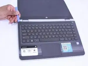
    • The keyboard is attached internally by clips. Use a small amount of force when removing the keyboard.

    • Use the Plastic Opening Tool to separate the keyboard from the base of the laptop.

  6. 6QdcixZ54hfSAaWW
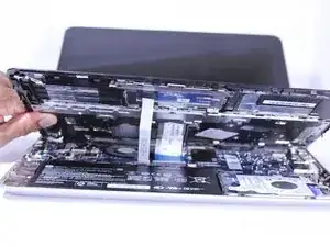
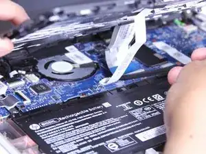
    • Raise the keyboard slightly to access the touch pad and keyboard cables.

    • Raising the keyboard too far or with excessive force may cause damage to the keyboard, touch pad cables, or their connectors.

  7. 1aDcZCZsqdBRT4Vf
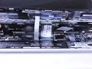
    • Disconnect the ribbon cables attaching the touch pad and keyboard to the system board (motherboard).

    • Using the Heavy-Duty Spudger lift up the plastic locks connecting the ribbon cable to the motherboard.

    • Use the blue plastic tab on the ribbon cable to pull it out from the lock on the motherboard.

  8. YOiNQ5J5dWZwvSgG
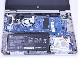
    • Lift the keyboard away from the base of the laptop.

  9. 2UAAkP1BlwGXK5Dx
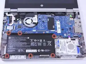
    • Using the Phillips 00 Screwdriver, remove 6 Phillips 2.0 x 4.6 mm screws from the perimeter of the battery.

    • Make special note of each screw and screw lock size and location during removal and replacement.

  10. xVkeRCgIawPWdweb
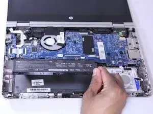
    • Carefully lift the battery up from lower right corner and disconnect it from the motherboard.

  11. 3WM6G1BjXIccMDpO
    3WM6G1BjXIccMDpO
    BFCTRFYngfvrPaGY
    viAFa6rduZOUbIhI
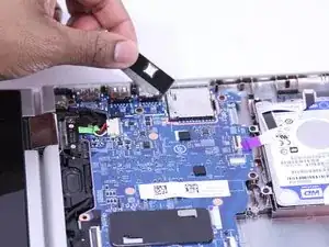
    • (You don't NEED to remove this shielding as you can remove the board with it still there.)

    • Remove the adhesive strip.

    • Lift the shield away from the base of the laptop.

    This step is not relevant or required...

    ETHREAL1 -

  12. iTfTRqfUs3LYPPvB
    iTfTRqfUs3LYPPvB
    yIXyYquYvTMmNyPV
    jBbYlaLfNx1k6NrE
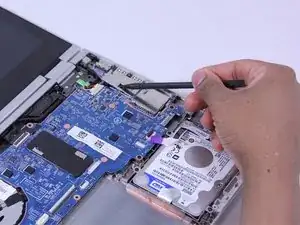
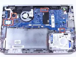
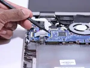
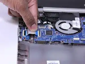
    • Disconnect the ribbon cables attached to the system board (motherboard).

    • Using the Heavy-Duty Spudger lift up the plastic locks connecting the ribbon cable to the motherboard.

    • Use the plastic tab on the ribbon cable to pull it out from the lock on the motherboard.

  13. kvOQypOvHviwWYrH
    kvOQypOvHviwWYrH
    b1dgMUV1RRp2ZJMv
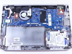
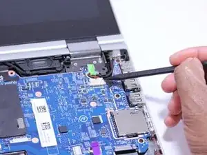
    • Disconnect the fastened cables from the system board (motherboard) by carefully pushing the cable's plastic edges using the Heavy Duty Spudger.

  14. tK1HM4BhZno2jPES
    tK1HM4BhZno2jPES
    JHvmABMUf52FXgN4
    • Pull the clipped cables from system board (motherboard).

  15. 3LJi2mDD36KjYRdU
    3LJi2mDD36KjYRdU
    cB1f5vLxqNAfkttD
    yN2amnwMeRZJfnsB
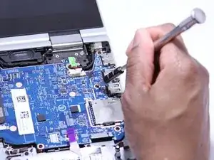
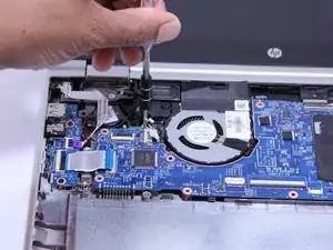
    • Remove the system board (motherboard).

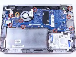
    • Using the Phillips 00 Screw Driver, remove 9 Phillips 2.0 x 4.7 mm screws with "M2L4" next to them.

    • Using the Phillips 00 Screw Driver, remove the silver screw.

    • Make special note of each screw and screw lock size and location during removal and replacement.

  16. 4PIALK3BctRndom6
    • Carefully lift the front side of the system board (motherboard).

    this step i do not understand. because you do no have to remove the motherboard for a screen replacement.

    Akeem Scrubb -

    This is the procedure for replacing the FAN, not the screen, and the board absolutely must be removed to replace the fan.

    Dennis Fain -

  17. AbqvScdieaXeZquW
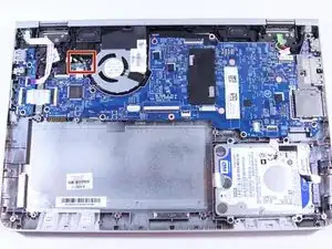
    • Using a Heavy Duty Spudger, disconnect the black and red RTC battery cable on the left side of the system board (motherboard).

  18. c6E3qrOexMtoSYjW
    • Release the system board (motherboard) from the base enclosure.

    • Place the motherboard somewhere safe since it is the most delicate and expensive part of the laptop.

  19. eFgXHBgIGkRCQPRo
    eFgXHBgIGkRCQPRo
    MFYjZL2DBeIKUdZO
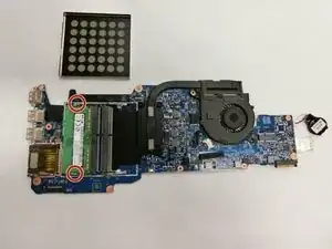
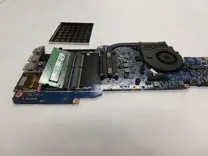
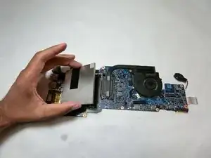
    • Gently pry off the metal container holding the RAM.

  20. obRAdjETChOcscAl
    obRAdjETChOcscAl
    mHEBqRBHUROVS3Fm
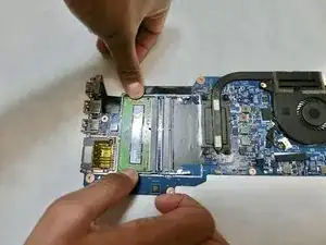
    • Push both tabs outward, so that the RAM pops up.

  21. Jn1RZMSYrkRKsCK2
    Jn1RZMSYrkRKsCK2
    GlAT4DAucgXq3CTX
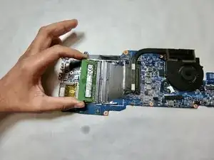
    • Gently lift the RAM out of the socket, retaining the 30 degree angle it rests at.

Abschluss

To reassemble your device, follow these instructions in reverse order.
Victor Samuel

Mitglied seit: 08/01/15

199 Reputation

0 Kommentare