Einleitung

The front screen of your HP tablet is the toughest thing to replace - you need to go through the rest of the tablet first, starting at the back and working your way forward. The same goes for the volume buttons. In this guide, you will be removing the following:

  1. Back Cover
  2. Battery
  3. Charging Port
  4. Speaker Unit
  5. Motherboard
  6. Front LCD Screen

Prepare your required tools, a new battery for your tablet, and set aside about 30 to 40 minutes to delve into the inner workings of your HP Slate.

  1. oyYuZHynPkfZKdpp
    oyYuZHynPkfZKdpp
    VWHBYdxAmNLBBLEq
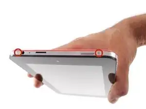
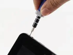
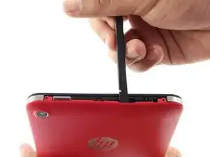
    • Begin your replacement by using a T3 or T4 Torx screwdriver.

    • Remove the two 1.4mm x 3mm Torx Head screws at the top of the device.

    On the HP 10 Plus 2201 there are no head screws. I used the spudger to 'carefully' separate the case. There are little snaps on the inside of case that will separate with little pressure on spudger.

    RB Richter -

    I used these directions to replace HP Plus 10 2201 battery. I bypassed speaker installation.

    RB Richter -

  2. E632GhJNVWIoWOEB
    E632GhJNVWIoWOEB
    NwLGaSd4dAfVDmbN
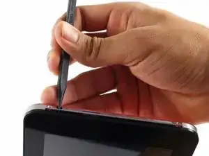
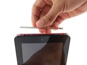
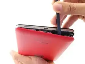
    • With the pointed end of the spudger, remove the thin metal band.

    • It is easiest to remove the metal band through the headphone opening.

    On HP 10 Plus 2201 there is no metal band. The case simply unsnaps apart.

    RB Richter -

  3. tTBhCKPal6DwANtH
    tTBhCKPal6DwANtH
    ILOygovSYpSNDSVq
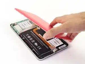
    • Using the flat end of the spudger, pry back the rear plastic cover.

    • As you work your way around the edge, several "pop" noises will be made. These noises are caused by the plastic clips coming undone.

    This is basically how I opened my HP 10 Plus 2201. "Using the flat end of the spudger, pry back (apart) the rear plastic cover from tablet.

    RB Richter -

  4. pQJLZCgkDpJZBawG
    • Remove the rear cover.

  5. GCKXs1DX2SJWPbW4
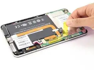
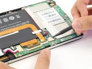
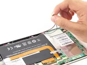
    • Locate and remove the yellow tape covering the red and white speaker wires.

    The inside of my HP 10 Plus 2210 looks similar but not exactly as this illustration

    RB Richter -

    The battery connections weren't the plug in type. The three battery battery wires (red, white, & black) were soldered into place,

    RB Richter -

  6. p6wnyhUAepKVTRWM
    p6wnyhUAepKVTRWM
    b6LxfDQBDFXElUtp
    • Using the pointed end of the spudger, push both sides of the speaker wire connector out of its base.

    • Push the same amount on both sides of the connector to avoid jamming or twisting its metal pins.

    • Do not yank or pull on the speaker wires, since they are fragile. Only push on the white connector.

    Do not pull on wires. Never force anything.

    RB Richter -

    note the route of the speaker cables round the battery

    Alan Boddey -

  7. P1WpoOHlYsk4CUlq
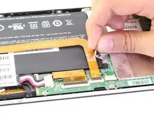
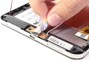
    • Gently pull back the foil covering the gold charging port ribbon.

    Hpcom Support Helps HP Printer users to download and install All Hp Printers drivers. We also provide all possible solutions to fix hp Printer problems. If you face any issue in install Hp printer driver or having other problems with the hp Printer, you can follow our 100 % working solutions. In case you can’t able to continue printing, then feel free to contact us. We are happy to serve you.

    hpcom us -

  8. ihlYYMpBQlsYaciH
    ihlYYMpBQlsYaciH
    rXofslcwLldga2Ak
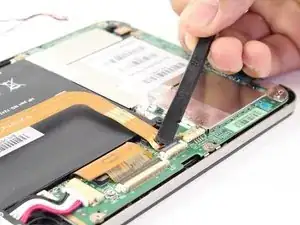
    • Using the flat end of the spudger, lift up the black panel covering the charging port connector.

    • Gently slide the charging port ribbon out from its housing.

    • It may be easier to use the pointed end of the spudger than your fingers.

  9. pIQfU5TndgTRjywE
    • Lift gold charging strip away from the battery.

  10. BQi2f4JckEJ4nA1s
    BQi2f4JckEJ4nA1s
    SpZ4dB1IkVpmgcGE
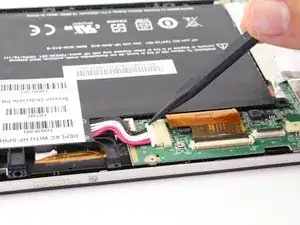
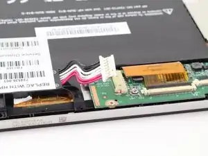
    • Push the white battery connector out of its housing using the pointed end of the spudger.

  11. 3SmKVAOfIeeQxlRS
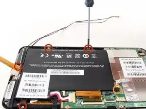
    • Using the #00 Phillips Head screwdriver, remove the 5 screws holding the battery in place.

    • The four 1.75mm x 3mm silver Phillips Head screws circled in red are interchangeable.

    • The black 1.75mm x 4mm Phillips Head screw must go back to the same spot during reassembly.

  12. nXdHS2EjOpFk3nCn
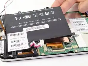
    • Lift battery out of its place and set aside.

  13. o6lFb5oSauIUaWYF
    o6lFb5oSauIUaWYF
    GnlDdLBkomnBtTV2
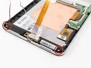
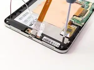
    • To free the speaker assembly, you will need a #00 Phillips Head screwdriver.

    • Remove the two 1.75mm x 3mm Phillips Head screws from the speaker assembly.

  14. ChT2un3BfB2gu6oX
    ChT2un3BfB2gu6oX
    3Tr64rBaQKeNCm2P
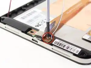
    • Pull back the foil overlapping the charging port to reveal another 1.75mm x 3mm Phillips Head screw.

    • Remove the screw with a #00 Phillips Head screwdriver.

  15. KAb1yfUoyMPUsET6
    • Lift the charging port and set it aside.

  16. FMUOLorZZSPvDYxG
    • Lift the two speakers out of the device and set them aside.

  17. HlhwRLf5Qxj5CFFM
    HlhwRLf5Qxj5CFFM
    2fxeAZDRPuKQEVGm
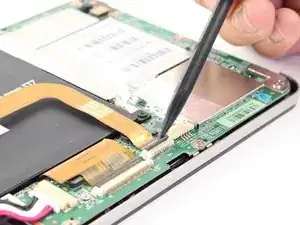
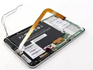
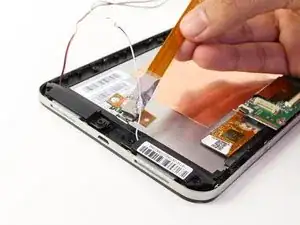
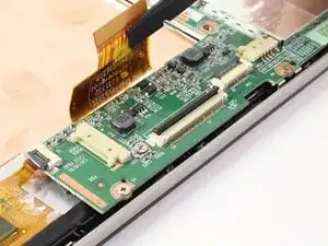
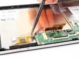
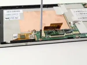
    • Disconnect the LCD screen ribbon by lifting up the black panel with the flat end of a spudger and sliding the gold strip out.

    • When reconnecting the LCD connector ribbon, make sure that it's pushed in all the way. If it isn't, there will be horizontal lines when you power the tablet on.

  18. OcBidygQPC4UfdDU
    OcBidygQPC4UfdDU
    XBm2RHHBeUveQjEK
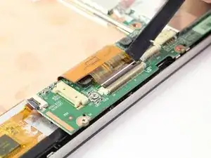
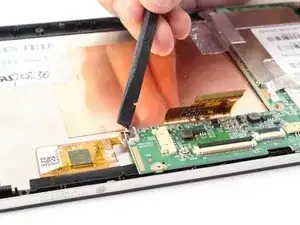
    • Likewise, disconnect the square radio chip ribbon by lifting up the black panel with a spudger and sliding the gold strip out.

  19. YmNNLPKscuRL1RKf
    YmNNLPKscuRL1RKf
    lYMJAjD2vCRlLNU4
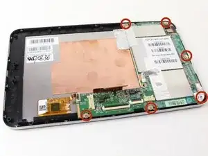
    • You will be using a #00 Phillips Head screwdriver to free the motherboard.

    • Remove the six 1.75mm x 3mm Phillips Head screws holding the motherboard to the screen.

  20. rVwiaSN4K1KXaGMF
    rVwiaSN4K1KXaGMF
    WfRBYHtnXWwLxPML
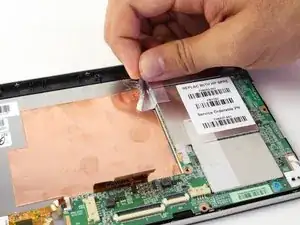
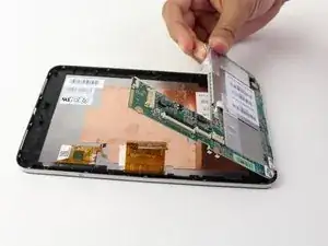
    • Using your hand, lift up the silver tape from the copper plate.

    • Lift the motherboard out of the device.

    • You may need to wiggle and work the motherboard to get it released from the device

    You will need to transfer the camera from the old motherboard to the new.

    Gently disconnect the connector marked “BYD”.

    Gently press down on the camera lens in order to release ir from the board and feed the connector through the motherboard by turning the connector in a diagonal position in order to feed it through the motherboard.

    rmeischner@comcast.net -

  21. KjDHVMV2gq3ejXNT
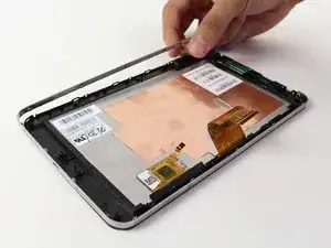
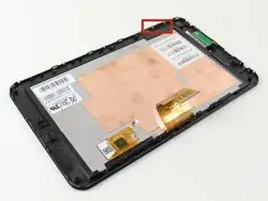
    • Remove the metal band surrounding the device by lifting it up out of the placement pins. Begin at one end and work your way around.

  22. TH1ficGV6HOkAFMY
    • You now have access to the LCD screen.

    • You can replace the volume rocker by lifting it up and out of the device.

    • The volume rocker should be reinserted so the "up" button is toward the top of the tablet during reassembly.

    Is it possible to only replace the digitizer or do I need to replace the whole part including the lcd?

    Marios Pitsillides -

    Unfortunately, replacing the digitizer alone is next to impossible without damaging the actual LCD screen, so the whole screen is what needs to be replaced.

    Zachary -

    Excellent instructions. My unit (Slate 7 2800) had a couple small pieces of tape from the motherboard to the case under the torx screws, but no trouble.

    Now the trouble. I'm replacing the front touch glass, and it appears to be glued into the case from the front side. I've tried carefully prying from the front around the edges and get a little loosening, but not enough to remove it. Is this the right approach? I assume that the display screen is just held captive in the well of the case and the touch glass. Do you have a thought to help?

    haavnry -

Abschluss

To reassemble your device, follow these instructions in reverse order.
Ryan ONeill

Mitglied seit: 11/04/14

2043 Reputation

0 Kommentare