Einleitung

  1. cBpPlZBdv6UbWFSI
    • Turn off the tablet and disconnect the power and all external devices from the tablet.

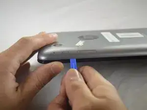
    • Position the tablet with the display panel down and the right side toward you.

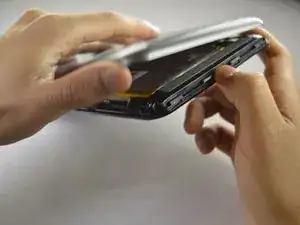
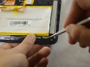
    • Carefully insert a plastic opening tool between the tablet cover and display panel assembly, separating the two components. The first insertion point should be between the power button and the volume buttons.

  2. WqEuyd1uBXyFfhCD
    WqEuyd1uBXyFfhCD
    REavbfcp3MRQOTO3
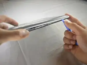
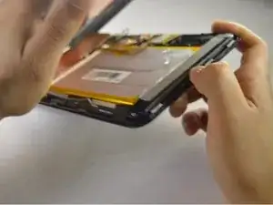
    • Slide the tool around the perimeter of the tablet until the edge of the cover is completely separated from the display panel assembly.

  3. nWfIMvGMtPhWPm2Z
    nWfIMvGMtPhWPm2Z
    AOMhKCV4RQOMumpK
    4CwLG4dE3mISC3hl
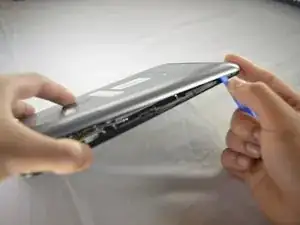
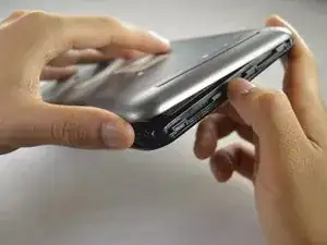
    • Pry open the back cover to take it off.

  4. 4C1EugFjQVMdlTeC
    4C1EugFjQVMdlTeC
    1YccpCOp5B31NZ3h
    QRPfghVPZAXHTdsw
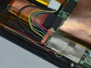
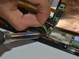
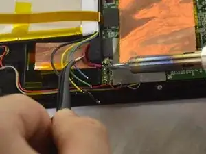
    • Disconnect the battery cables from the system board by desoldering them. See iFixit guide on how to solder.

    • The battery cables are soldered to the system in the following sequence, top to bottom: red, blue, green, yellow, black.

  5. 6GEVHMRuNWdWZeSh
    6GEVHMRuNWdWZeSh
    NSCBaPgANnL1XUcV
    oUh6gDDkkLUMPX6x
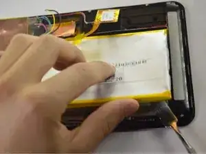
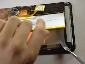
    • Insert a nylon spudger between the battery and the display panel assembly. Carefully pry the battery up and remove it from its place.

    • The battery is attached to the display panel assembly with double-sided adhesive. Make sure to firmly pull the battery.

    • The regular black nylon spudger should be used whenever possible, especially around batteries.

  6. FsgsLchm2JdyP2Ck
    FsgsLchm2JdyP2Ck
    4LIxWSPJK5Co2DBo
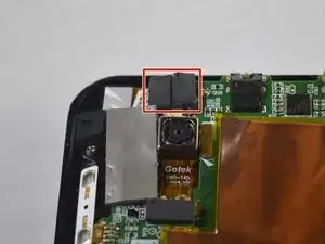
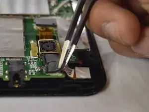
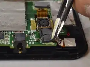
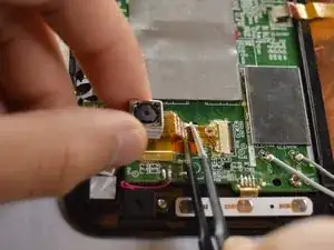
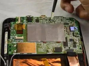
    • Use tweezers to remove the black foam stickers from the front facing camera to expose the wiring.

  7. Y6OjMqftuP1R2tKd
    Y6OjMqftuP1R2tKd
    MCUTl2RqVTGGlv5X
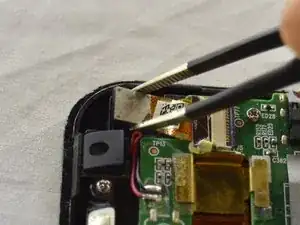
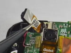
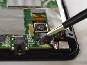
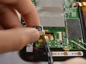
    • Lift the camera out from system board and firmly pull the wire out from the connector.

  8. AgKJHMgpEri1TL1Z
    AgKJHMgpEri1TL1Z
    LXhDTMQDjxyNmRd3
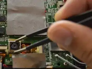
    • Use the tweezers to remove the black foam stickers from the rear facing camera to expose the wiring.

  9. QqNbJiqvYjUlbgI1
    QqNbJiqvYjUlbgI1
    uDsUMMAMDsBTFfQX
    • Using tweezers, lift the camera out from system board.

  10. YvgsrYpNlmwMVyCB
    YvgsrYpNlmwMVyCB
    1WKYfqJILFlrP3ul
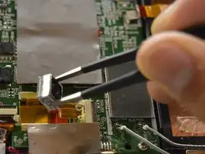
    • Use tweezers to pull the wire out from the connector. Pull away from the connector, parallel to the tablet.

  11. BtMPUcVskYys1cNC
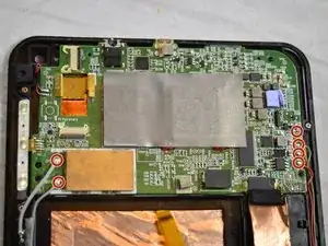
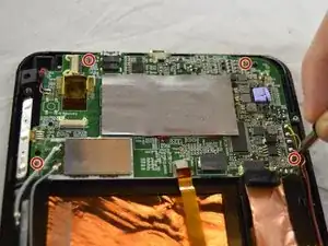
    • Remove the four screws from the motherboard using a Phillips 00 screwdriver.

  12. XPjuwGmXdixKjw6T
    • Remove the two grey wires on the left and the four multicolored wires on the right by desoldering them. See iFixit guide on how to solder.

    • The multicolored wires are in soldered in order from top to bottom in the following order: yellow, grey, black, and red.

  13. slZuuAlHrvkcCPbl
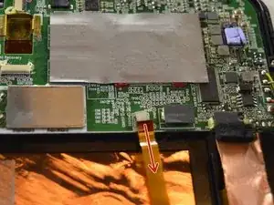
    • Disconnect the LCD wire from the connector by pulling away from the connector, parallel to the tablet.

  14. wlJulJHIhbTVMq1f
    wlJulJHIhbTVMq1f
    6KTAFSlv3EVdiVZx
    • Using tweezers, lift the system board and remove it.

Abschluss

To reassemble your device, follow these instructions in reverse order.

Jessica Andrade

Mitglied seit: 04/10/16

839 Reputation

Ein Kommentar

gracias x las imagenes , fueron de mucha ayuda
miguelangel131178 -