Einleitung

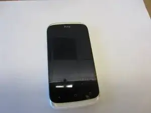
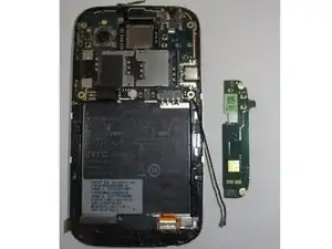
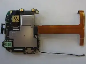
This guide will outline how to remove the logic board assembly, including cables, from the HTC Desire V smartphone

  1. 51UrWKe4ktasnGHl
    51UrWKe4ktasnGHl
    NcHfrTgsUoRva6yI
    CA2DpcYNmDrYDjIl
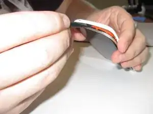
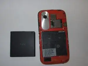
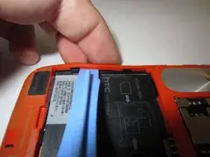
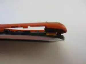
    • Gently pry back cover away from phone.

    • If you are having difficulty you may need to use a Spudger or plastic opener.

  2. mAdXU5TFQInQ1ixx
    mAdXU5TFQInQ1ixx
    LQ4hhGBKKL5KAA1q
    v6UpMKFlvyCaixIU
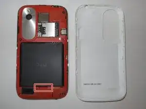
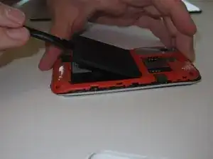
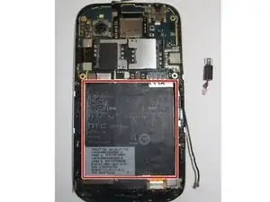
    • Lever the battery out from the bottom end first.

    • Do not bend or puncture the battery.

  3. WIlCGYDnPjv5VXJo
    WIlCGYDnPjv5VXJo
    2LJ1VADkNpWPf66i
    Y33LPJsHfbZcDZad
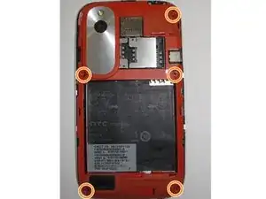
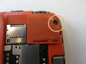
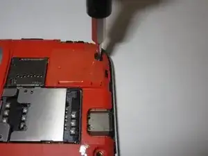
    • Use a Torx T5 screwdriver to unscrew and remove five 3.0 mm screws from the rear frame.

  4. 5iBYSrxNxjSAHvPp
    5iBYSrxNxjSAHvPp
    5Tkxhhd42vMuIYQl
    iQknLDAvqCRCYlnX
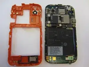
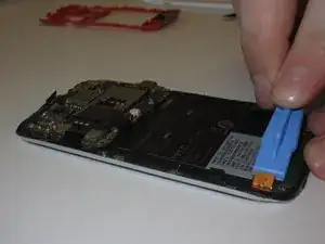
    • Use an opening tool or a spudger to gently remove the rear frame.

  5. uVLGQbqtXtJJkSlE
    uVLGQbqtXtJJkSlE
    KE4gvBofJjI4FXpq
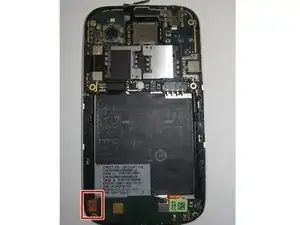
    • Remove the connector on left side of the Navigation board by unplugging/prying the orange ribbon.

  6. EGeQmiJSiYmEiNJt
    EGeQmiJSiYmEiNJt
    WrQWDIRUYSwgqsVO
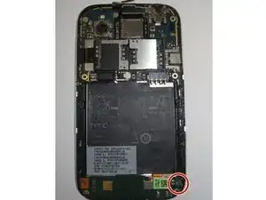
    • Gently unplug and remove aerial cable (black antenna) from bottom plug.

  7. BVrZuBkY2NoBUVAJ
    BVrZuBkY2NoBUVAJ
    hTo2DhuGcn2qIfVS
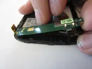
    • Nav Board will be stuck down by glue.

    • Pull gently from the right end of the board, being careful of its flexibility.

  8. jah4OfQoGaNVMJBF
    jah4OfQoGaNVMJBF
    RXRbWAigJRGaPB3D
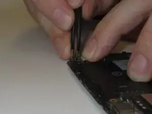
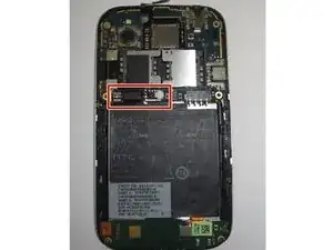
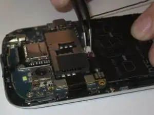
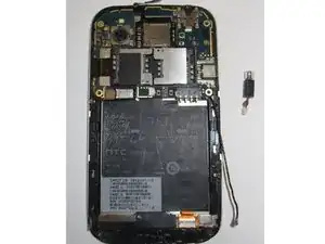
    • Unplug the vibration motor shown from the white plug on the motherboard.

    • You will probably need tweezers to do this.

  9. vDcP3oW4COLn5QeN
    vDcP3oW4COLn5QeN
    PfMWNrH2R4bT2eON
    • Gently remove the motor from its housing in the phone’s chassis.

    • The easiest way to do this is to lever the motor out by its rotating end using the tweezers.

  10. ikGorcecJnXwJarh
    ikGorcecJnXwJarh
    TttxWIJrEkgq6mHa
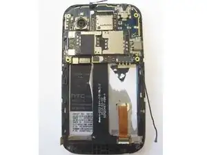
    • Remove the black information sticker if this is the first time opening the handset.

  11. jK4cSQ4cacEuxGTT
    jK4cSQ4cacEuxGTT
    tJgEUicEqEYdxcbk
    YxIu26lNcRoumxJC
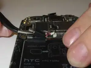
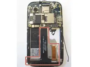
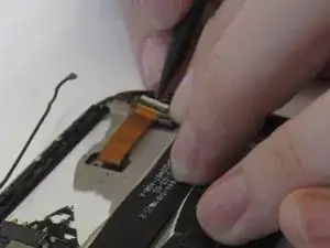
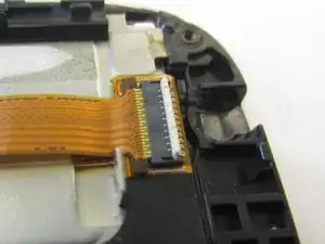
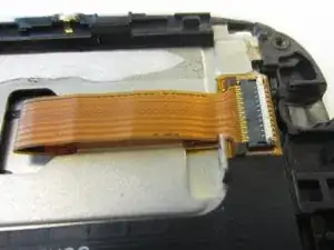
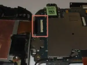
    • You should now see a black ribbon cable, which was connected at the left to the Nav board, and on the right, to a gold ribbon cable which goes to the screen.

    • Unlock the gold ribbon cable connecting screen to logic board by lifting the locking tab at the back of the socket.

    • For this you may wish to use a spudger or tweezers.

  12. c16kmb51jheruvjN
    c16kmb51jheruvjN
    rS6OjTAixUvmAKyE
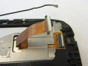
    • Disconnect gold ribbon cable connecting screen to logic board by pulling cable out gently.

  13. GMKtSQqOXUyrk2CT
    GMKtSQqOXUyrk2CT
    UboCihY5tJy3EkXW
    xGwggrcuQOeI2qt1
    • Gently unstick black ribbon cable from the chassis.

  14. pwRybxIT1Kc4pUIn
    pwRybxIT1Kc4pUIn
    d4ihPo2JUUKlmaGJ
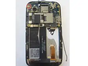
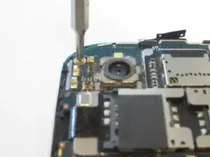
    • Unscrew the 2mm silver screw from top left.

    • Use a Phillips PH00 Screwdriver for this.

  15. GrJROHjwNFECwF1J
    GrJROHjwNFECwF1J
    pKcViCH6hWsZolhk
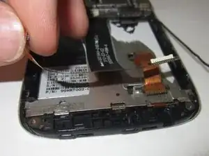
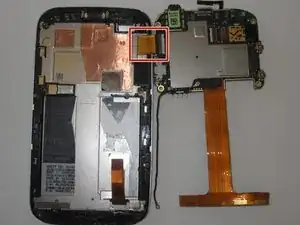
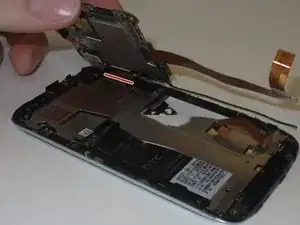
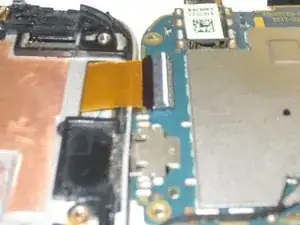
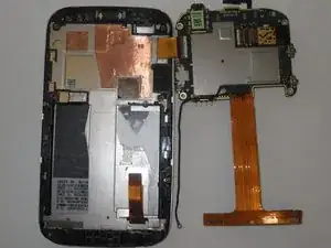
    • Gently pry logic board from the casing by lifting the left side up, as if there was a hinge on the right, folding it over the right edge where you will see a gold/orange ribbon cable.

  16. trhPfkjHYVdIyCQF
    trhPfkjHYVdIyCQF
    TMBeBRiwBEGL5acw
    uXxrUfSKYiJFMfhB
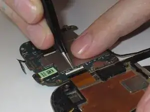
    • Remove the gold ribbon cable by lifting tab at the back of the socket, using a spudger or tweezers.

  17. ELEs2CKxaychKpAA
    ELEs2CKxaychKpAA
    AJB3BBUwRms5RwK5
    • Gently pull the logic board to the right and it will disconnect from the chassis.

Abschluss

To reassemble your device, follow these instructions in reverse order.
William McCusker

Mitglied seit: 29/01/15

1096 Reputation

0 Kommentare