Einleitung
Prerequisite guide used for tearing down device.
Werkzeuge
-
-
Power off the device.
-
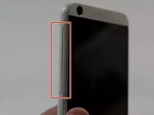
Locate the SD Card/SIM Card cover flap on the left side of the device.
-
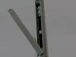
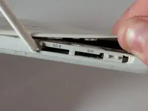
Upon opening the cover flap you will find slots for SD Card and the SIM Card. Carefully remove these items if your device has them and set them aside.
-
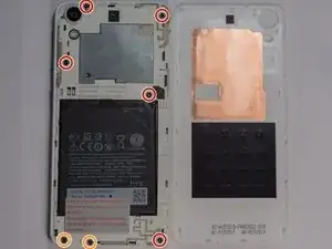
Lift on the back cover to begin the removal process. Continue removing the back cover by working along the edge. Once removed set aside the back cover.
-
-
-
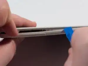
Place a plastic opening tool along the seam of the front plate and back plate. Run the opening tool along the seam while prying slightly in order to pop the plastic clips away from the front plate.
-
Once one or two clips have popped away you may begin to use your free hand to apply additional pressure while continuing to apply prying pressure as well with the opening tool.
-
-
-
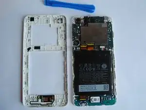
Continue working your way around the seam between the two parts and eventually you will be able to separate the entirety of the backplate revealing the internals of the device.
-
-
-
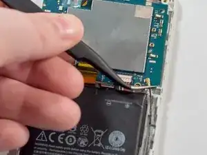
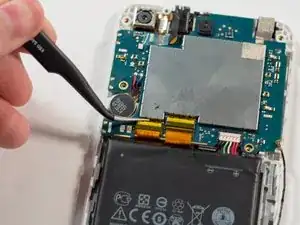
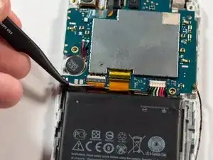
Using the tweezers, remove the antenna connection. Grab the connector by the base and pull towards the head of the connector.
-
-
-
Remove the tape that sits on top of the left connector.
-
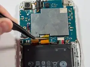
Place the tweezers around the ribbon cable and apply even pressure away from the connector to disconnect the cable.
-
-
-
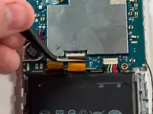
Remove the tape that sits on top of the right connector.
-
Place the tweezers around the ribbon cable and apply even pressure away from the connector to disconnect the cable.
-
-
-
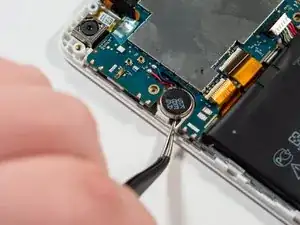
Using the tweezers or another small pointed tool, place the tip under the edge of the round disk-like component on the left side of the device. Apply a small amount of pressure to the edge of the component to dislodge it.
-
-
-
Place the plastic opening tool along the edge of the components and lightly pry these components out of their slots.
-
-
-
Note the location of the plastic clips.
-
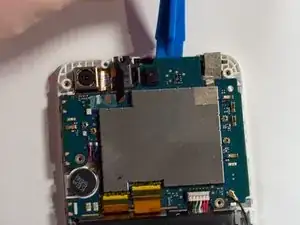
Place the plastic opening tool along the top of the upper logic board. Apply even gentle pressure to remove the logic board from the rest of the device.
-
To reassemble your device, follow these instructions in reverse order.
