Einleitung

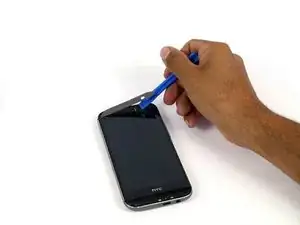
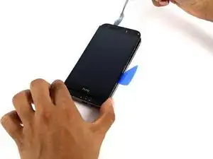
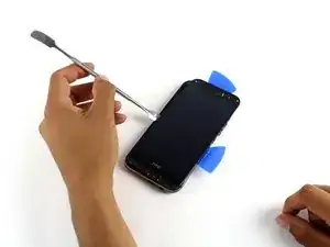
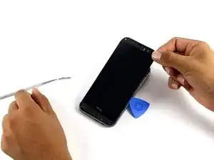
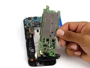
Diese Anleitung zeigt, wie man die Hauptplatine eines HTC One M8 tauscht.

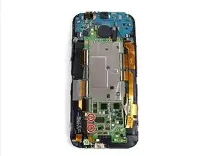
Es könnte sein, dass dein Gerät eine Menge Kupferabschirmung und Klebeband enthält, so wie hier gezeigt. In diesem Fall musst du alles vorsichtig entfernen um an die Hauptplatine zu kommen.

  1. 4uTAnfGyxtijjQ1f
    4uTAnfGyxtijjQ1f
    qwFgZwWRsJ6KUlhj
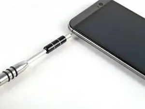
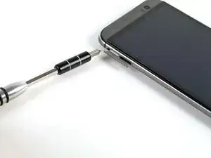
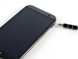
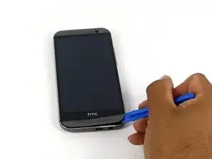
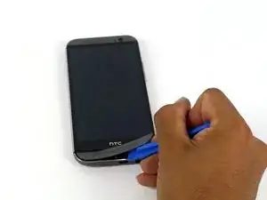
    • Stecke einen Auswurfstift für SIM-Karten oder eine aufgebogene Büroklammer in das kleine Loch an SIM-Karte Einschub, welches du links oben am Telefon findest.

    • Drücke damit hinein, damit der Einschub herauskommt.

    • Dafür braucht man durchaus etwas Kraft.

    I just successfully completed the battery replacement on m8 using this guide…thought I would add a comment at each step to follow my story. This step of course should be easy if you’ve put the phone back together.

    Ashley Keith (sc0rch3d) -

    My HTC m8 doesn’t have a SIM card, and it might not have a micro SD card, since i can’t back anything up on it. Does not having the SIM card or the micro SD card matter in disassembly and reassembly?

    Lewwy Ignovoir -

  2. FRXkaFwTtZH1CHKQ
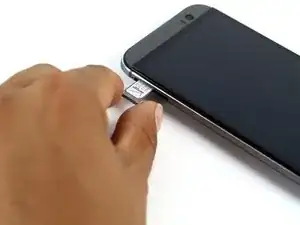
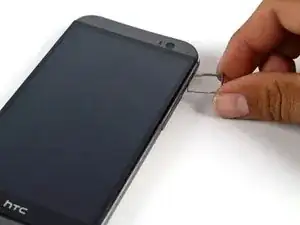
    • Entferne den Einschub aus dem HTC One M8.

    • Achte beim Wiedereinsetzen darauf, dass die SIM richtig orientiert ist.

    My phone have a problem from sim card rejected ,

    shola -

    Another easy step if you have the right tool

    Ashley Keith (sc0rch3d) -

  3. 4CFQNL5baNtxLuyI
    4CFQNL5baNtxLuyI
    oeYFRPVliqG6gIhY
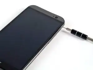
    • Stecke einen Auswurfstift für SIM-Karten oder eine aufgebogene Büroklammer in das kleine Loch am MicroSD-Karten Einschub, welches du rechts oben am Telefon findest.

    • Drücke damit hinein, damit der Einschub herauskommt.

    • Dafür braucht man durchaus etwas Kraft.

    another easy step if you have the right tool

    Ashley Keith (sc0rch3d) -

  4. 3gqFoAxPHm3cDBSS
    • Entferne den Einschub aus dem HTC One M8.

    • Achte beim Wiedereinsetzen darauf, dass die Karte richtig orientiert ist.

    another easy step if you have the right tool

    Ashley Keith (sc0rch3d) -

  5. HlbeTVCOOEoQGCQW
    HlbeTVCOOEoQGCQW
    UB1fQvvW5OYFJNqD
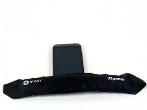
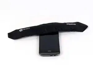
    • Benutze einen iOpener oder eine Heißluftpistole, um den Kleber an den oberen und unteren Lautsprecherabdeckungen aufzuweichen.

    • Die iOpener Anleitung zeigt, wie man den iOpener benutzt.

    I used a heat gun settings 200 at 75, but I also found using a hair dryer works just as well. Heated up the bezels came right off and for putting back on I heated it back up and they have stayed put.

    Jason Cobb -

    I used a hair dryer for this which worked fine but I didn't need to heat it for as long as I did. 10-20 seconds is enough to start. I didn't realise how hot it would get so after heating for 90 seconds on high heat the phone was absolutely roasting and I've got two spots of heat damage on my screen. Still all works though luckily.

    Ian -

    Disassembly: I did NOT use any heating elements. I have a straight edge razor (like you use to scrape off window decals). Gently push in 1 point of the straight edge and work in the rest of it. Then use a spudger slowly to remove the grills.

    Assembly: Enough adhesive should be left to reinstall the grill with no problem. Be careful align it perfectly then don’t be afraid to give a good push into place.

    Ashley Keith (sc0rch3d) -

    What are the speaker grilles?

    Lewwy Ignovoir -

  6. 2YsuBPkZFkn3tTKp
    2YsuBPkZFkn3tTKp
    VoHpohwMpRK2Xuuu
    HccAba2fnRMUhnud
    • Mit einem Plastiköffner kannst du vorsichtig die untere Lautsprecherabdeckung ablösen.

    • Der Kleber ist verschmiert und sollte mit einem Reinigungsmittel ganz entfernt werden.

    Disassembly: I did NOT use any heating elements. I have a straight edge razor (like you use to scrape off window decals). Gently push in 1 point of the straight edge and work in the rest of it. Then use a spudger slowly to remove the grills.

    Assembly: Enough adhesive should be left to reinstall the grill with no problem. Be careful align it perfectly then don’t be afraid to give a good push into place.

    Ashley Keith (sc0rch3d) -

    You need to get between the thin black rim and the grey speaker cover, not between the metal and the black rim.

    Nebuar -

  7. kUMBx3hCpAHyCBNF
    kUMBx3hCpAHyCBNF
    WeT5ePxlt5HRGG1Z
    • Mit einem Plastiköffner kannst du vorsichtig die obere Lautsprecherabdeckung ablösen.

    Be careful on these steps to not bend the grill while removing.

    Ashley Keith (sc0rch3d) -

    What is the strip of tape for under the grill? Mine has snapped off completely

    crabonarock -

  8. S6QVUODFAqm1towZ
    • Entferne die zwei oberen silbernen 3 mm PH00 Schrauben.

    • Entferne die vier unteren schwarzen 4 mm T5 Schrauben.

    The markers on step 8 were wrong. The 4 black TX screws are actually all in the bottom, while the silver screws are on top.

    WP7User -

    Nice good good

    tamerseleman68 -

    Do yourself a favor and get a proper set of small screwdrivers including smaller Torx bits T5-T10 (especially with magnetism)…you’ll thank me later. Getting the cheap kits from Amazon or included in the order will likely not work or strip easy.

    Disassembly: be easy with the screws and don’t strip them. organize your workspace. i put the top screws next to my top speaker grill on the left of my workspace (and worked left to right…so that assembly was right to left) and bottom torx next to my bottom speaker grill.

    Assembly: be easy with the screws and don’t strip them. you will definitely feel the stopping point and don’t add extra torque.

    Ashley Keith (sc0rch3d) -

    My 2 silver Phillips screws at the top are PH #000, not #00.

    At the top be careful about moving the camera lens cover.

    At the top and bottom, be careful about peeling or lifting off the speaker covers.

    Qrash -

  9. DyXVX2TwYxsSXbXS
    DyXVX2TwYxsSXbXS
    INBdOPirewhtHqn2
    GQGYJeQ3KD62PIkb
    • Um die Klammern zu lösen, die die Rückseite festhält musst du dich mit einem Spudger und einem Plastiköffner rings um das Telefon herum arbeiten.

    • Im Bild ist ein Metallspatel gezeigt, ein Plastiköffner ist aber besser, da er weniger Schaden zufügt.

    • Verliere nicht den Einschaltknopf, er sitzt lose oben im unteren Gehäuse.

    • Eventuell brauchst du ziemlich viel Kraft zum Trennen.

    Note: the pictures make it look like it's the glass the comes loose from the body. In fact, it's the metal shell the comes off, while all of the electronics are attached to the face. To get it started, you have to dig your spudger in between the metal shell and the little plastic rim that goes around the glass. I found it easiest to start in the middle, below the volume buttons.

    Kael Shipman -

    I wish this was more clear in the picture. I ended up cracking my screen/digitiser trying to pry the glass open... the more you know!

    NzUddin -

    I tried starting by the volume buttons but was having no luck. I found starting just under the sim card worked best. Raising the whole side and the top up allowed the rest to come out. Be mindful of the charging port at the bottom and don't force the bottom out first but rather lift the top end out then the charger will clear. Same goes for putting back together. Charger port in first them push down on the sides and top.

    Jason Cobb -

    I used guitar picks to wedge inside the case as I prised it open

    Ian -

    Why do they design it to make it so difficult to replace the battery?

    Rich Hanes -

    Disassembly: did not use any heating elements. used my straight edge razor near the top left side opposite the volume rocker (it should go in pretty far and worked until i heard the first clip pop. worked around the top and down the right side. as others mentioned, you’re getting the top loose then rocking out the unit to not screw up the charge port. DO NOT LOSE THE POWER BUTTON.

    Assembly: hold the shell with charge port up and place the power button (this keeps it from falling out while assembling). put charge port in first then slowly work your way around the side little by little. I started hearing the clips pop into place maybe as I working around the perimeter on the 3rd try. after that, give it some good force as the unit should almost be flush with the shell.

    Ashley Keith (sc0rch3d) -

    After destroying the tip of three nylon spudgers, I would like to advocate using a METAL spudger, as shown in the picture. Just be careful to minimize scarring of the metal cover. But, the nylon spudger definitely is not strong enough to release the chassis, especially since these phones tend to be pretty old and set in their ways at this point in time. With a metal spudger, I was able to separate the back from the chassis in just a few minutes, after spending over 30 minutes failing with the nylon spudgers.

    christopher e m -

    Not sure g enough for any of this work. Mine are nubs now. And left residue around the edges that I was trying to pry loose.

    loritankersley337 -

    Please tell me, how to put in the Power Button. It’s not symetrical.

    I would appreciate a picture of it in it’s housing or a discription.

    Th.Laahcs -

    I found that on my HTC M8 the power button needs to be a shade to the left. You can figure it out on your model by looking for the button by using a Sim Card eject tool and pressing on the power button which on my model was covered by black tape. You’ll feel the button click/press once you find it - you can then determine if the button is a shade to the left or right when you line it up with the housing with no power button. Place the phone temporarily into the shell and you’ll be able to determine the button placement, this is how I did it.

    Hector Vera -

    I too also used a metal spudger on the left side opposite the volume rocker, that seems like a good spot to start.

    Hector Vera -

  10. MoYtwWaBgQ1Is1Oh
    MoYtwWaBgQ1Is1Oh
    VBUUkTOQ2LLKDlkp
    • Drehe die beiden silbrigen 2 mm PH00 Schrauben heraus, die den Akkustecker auf der Hauptplatine sichern.

    • Löse den Akkustecker vorsichtig mit einem Plastiköffner ab.

    This caused a bit of grief for me on the reassembly. Be very mindful of the battery connector when installing the new battery. Look closely at the connector there is what appears to be a diode on the underside that needs to mate with proper contact to another diode on the motherboard. This is what actually allows communication between the phone and the motherboard. If this connection isn't mated properly you will get a 0% indicator on the screen and no charging occurring. Also the orange LED will flash 6 times and repeat. I suggest before placing the phone back together completely in the case to screw the motherboard back together and attach all ribbon cables and mate the battery. Then plug it in a charger and make sure you get proper battery communication and charging. DO NOT power on the phone at this point. Unplug the charger and put everything back together and you should be ok.

    Jason Cobb -

    I have 2 of these devices and both had Philips #000 screws holding the battery connector in this picture. If the screw doesn’t catch and turn easy then try #000 or else you risk stripping the head.

    Stewart Diamond -

    Jason Cobb’s tip is key. You saved me a lot of trouble, thank you! I didin’t get the connector mated properly at first, and that quick check let me find out. Got it the second time, the screen showed the battery percent and the normal charging screen.

    Eric P -

    Disassembly - pretty easy, don’t strip the screws and use spudger. The pictures do not show that you might have a small rubber gasket on the screw closest to the charge port…KEEP IT. I also had a white wire that attached just above the charge connector.

    Assembly - as Jason said…the most frustrating part of assembly was getting that dang connector aligned into place. Put the white wire and gasket back in place before attempting. I gently used my fingernail until I felt it on the connector then had to give it a GOOD amount of force to pop in. then add the screws.

    Ashley Keith (sc0rch3d) -

    Extra note on assembly - as mentioned above, this is a great spot to stop and connect to charger without powering on. you should get a solid orange light and charging icon / percentage on the screen. make it quick with the connect and disconnect

    Ashley Keith (sc0rch3d) -

  11. intXrUK1LEfsfs4c
    intXrUK1LEfsfs4c
    uQgBEJAglafYOx2t
    2hJUxw5trZ5WBt5U
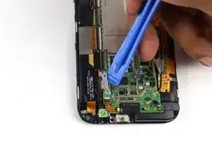
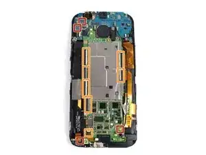
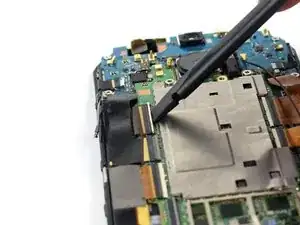
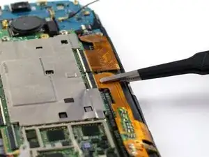
    • Mit einem Spudger kannst du die zwei (vier) Antennenkabel lösen.

    • Benutze die Spitze des Spudgers um die sieben ZIF Verbinder zu öffnen.

    • Die sieben Flachbandkabel kannst du mit einer Pinzette vorsichtig von ihren Verbindern trennen.

    All my connectors were covered in fibrous copper tape

    Karl Horton -

    In mine, there were also two cables connecting at the top left of the motherboard to the daughterboard above as well, and where there is only one antenna cable in the bottom left of the default image, there were two.

    William Miceli -

    Tape covered my whole assembly as well and the antenna cables were the same as previous poster.

    Jason Cobb -

    The two cables at the top of the motherboard near the camera, mentioned by commenters above, will have a small rubber pad on top of them. You may wish to keep that pad. Also not pictured here is the LED surround. It can easily come loose from the motherboard. Don't lose that either.

    Alex LeDonne -

    I accidentally broke the ribbon cable in the upper left that dives under the blue daughterboard. I'm not sure how, but it was probably trying to get the tape loose. The only problem it seems to have caused is that the proximity sensor (next to the front-facing camera) doesn't work and neither does the notification LED.

    KC Baltz -

    Hi im trying to locate on internet the ZIF connector for the digitizer but its impossible to know how many PINS does it have can you help ?

    Pawel Pieta -

    Mine was covered in tape as well. I gently pealed it off and managed to leave most of it intact for when I put it back together. Also had the two cables connected at the top left, they can be detached and reattached in the same way as the other two at the bottom. Just lift them off using a spudger when detaching then hold them in place with tweezers whilst pushing down on top with a small screw driver until it clicks in when reattaching.

    Ian -

    Disassembly - I was one of the lucky ones to have pretty much this ENTIRE SPACE covered in tape. I peeled off the middle pieces completely using spudger and tweezers. for the ones over the ZIF’s….i peeled enough off to get them free then I used tweezers to lift the excess tape and my straight edge razor to cut the excess. be careful especially around the volume cables if tape is on them. At this point, disconnect the black cable on the right at the bottom and fold it away, then tackle the disconnects. the top left disconnect will be your worst enemy b/c the cable is folded under the mother board. be gentle.

    Assembly - use tweezers and spudger to get the connectors back in…double check all of them. I did the top left one first as i knew it would frustrate me the most. the rest went quick and easy.

    Ashley Keith (sc0rch3d) -

    Reassembly: Before screwing the motherboard back down, connect the top left ribbon cable back into its connector. This will save you a lot of heartache, because the top left ribbon cable is just too short to force into the connector once the motherboard is screwed in.

    Daniel Handojo -

  12. YU2USokMP5fPKgDt
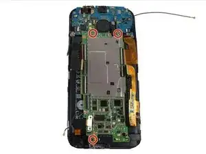
    • Entferne die drei silbrigen 3 mm T5 Schrauben.

    Disassembly - Before the screws, mine had 2 wires connected (black and white) connected to motherboard at the top left. remove those first and make note of which ones goes where. then take out the screws. thankfully these are longer than the previous t5 screws, so you won’t mix them up. I also had tape covering part of the LEDs and extending onto the black microchip to the top left.

    Assembly - put the screws then the wires.

    Ashley Keith (sc0rch3d) -

  13. GFJXKgFtMClqbtCr
    GFJXKgFtMClqbtCr
    nSWH3Sn4FYKRDsee
    No1jt4YyfSNHX1US
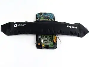
    • Benutze einen iOpener oder eine Heißluftpistole um den Kleber aufzuweichen, der die Hauptplatine an der Display Einheit befestigt.

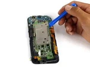
    • Benutze einen Plastiköffner um die Hauptplatine vorsichtig von der Display Einheit zu trennen.

    • Der untere Lautsprecher ist immer noch mit der Hauptplatine verbunden. Wenn du nur die Platine selbst tauschen willst zeigt dir diese Anleitung, wie man den Lautsprecher überträgt.

    Disassembly - did NOT use a heating element. GET THE ZIF WIRES OUT OF THE WAY at this point. I started at the top middle with a pick and spudger then worked my around the right of the motherboard. gently lifted it out from right to left using spudger as needed to remove from battery.

    Assembly - placement is critical here between all the wires. I started by putting the motherboard bottom in place then laying it down watching each wire was positioned correctly as I went.

    Ashley Keith (sc0rch3d) -

    Oh C'MON,YOU HAVE GOT TO BE KIDDING ME

    janecooper915 -

Abschluss

Um dein Gerät wieder zusammenzusetzen, folge den Anweisungen in umgekehrter Reihenfolge.
Michael Gonzalez

Mitglied seit: 14/04/15

4391 Reputation

2 Kommentare

Thanks you very much

ngvhiem26 -

all ok. thanks.

Javier -