Einleitung

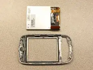
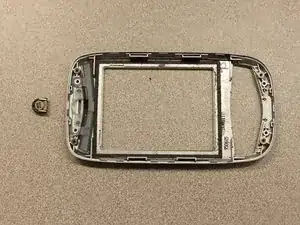
This guide will explain how to install / remove the receiver on the HTC Wizard 200.

  1. GauhfFXWK5KLTSlL
    GauhfFXWK5KLTSlL
    XlCuwUISUsa1O5Zr
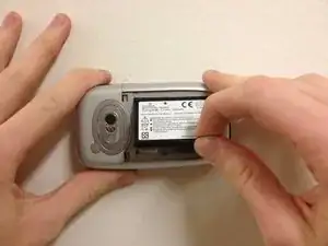
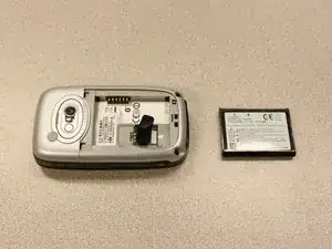
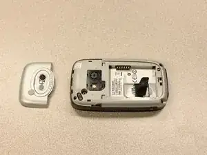
    • To expose the battery, remove the outer case with your fingernail.

    • Remove the battery by pulling the black tab.

  2. sE6E1ZyBsijxyq4O
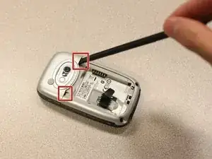
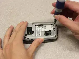
    • Insert the flat end of the spudger into the two notches on the back of the camera cover and pry them up.

  3. wHVMY2W3FtFEwncD
    wHVMY2W3FtFEwncD
    jdMSwEVjx5veEjJI
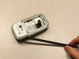
    • Work the spudger around the edges of the camera cover until it comes off.

  4. lkLZ2NdABKFtUKAu
    lkLZ2NdABKFtUKAu
    HWNjOJZFQSZyhJB1
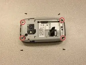
    • Remove the four 6 mm screws with the T5 Torx screwdriver.

    • One of the screws is under the "void" sticker.

  5. jqbOZTMNGN5QgHCy
    jqbOZTMNGN5QgHCy
    O1wgPM3aLFwUMlZP
    1peypbbeZ3352Lti
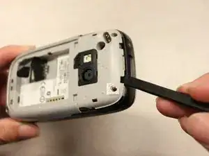
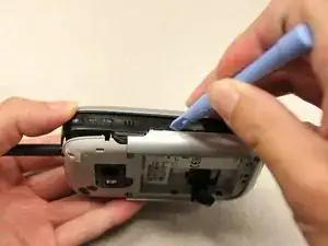
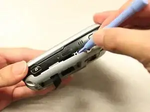
    • Insert the flat end of an iFixit opening tool between the side and inner covers to create a gap.

    • Work the tool around the edges until all the clips release.

  6. QHJ25swWJOBHtsiA
    QHJ25swWJOBHtsiA
    PsoD3MvrNHNmeAQE
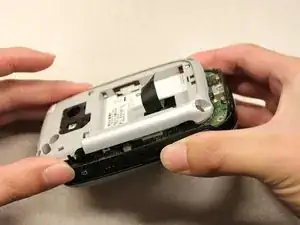
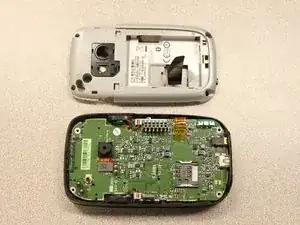
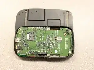
    • Once all the clips are open, remove the inner panel from the phone.

  7. CPWWwg5g3BQDVYQw
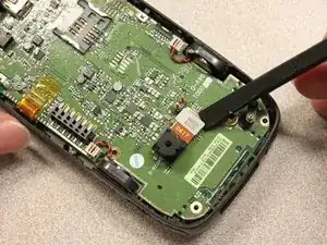
    • Use the spudger to pry the camera off.

  8. ATltjHt6ERinFZGN
    ATltjHt6ERinFZGN
    siHOCqb3uOtayxhm
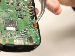
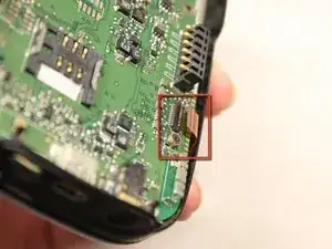
    • Using tweezers, flip the connector latch away from the motherboard.

    • Detach the flexible connection from under the connector latch.

  9. 2DPu1syJMtul5XPp
    • Slide the keyboard into the open position.

  10. CPoCVF62p2SDORVE
    CPoCVF62p2SDORVE
    QTyyTWXmEYPhNLrR
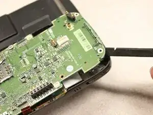
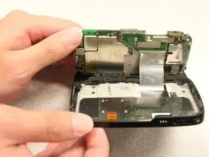
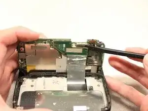
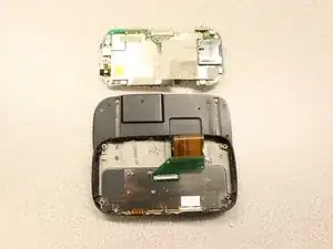
    • Lift the motherboard out of the case using the spudger.

    • Expose the underside of the motherboard using your hands.

  11. jSGXQBrfGaGhASWC
    jSGXQBrfGaGhASWC
    vQh2oJydx1VTtLSX
    • Remove the flexible connection from the motherboard.

    • Caution: Removing the connection too fast may cause damage to the connection and cables.

  12. eRQnmHP1hNgugWqX
    eRQnmHP1hNgugWqX
    3FpxbDPDlOlaMPdO
    uBRUDGQp2XH3hZrF
    • Remove the four 5mm screws with the T5 Torx screwdriver.

    • Remove the keyboard slider from the main body.

  13. lU46fFiO6alnIrgy
    lU46fFiO6alnIrgy
    gQhMHGY2GXoDCZaI
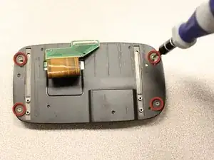
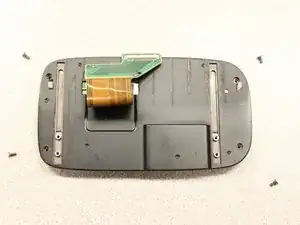
    • Use the T5 Torx screwdriver to remove four 5mm screws that secure the back of the screen casing.

  14. Qbj3IHxrwe2higYS
    Qbj3IHxrwe2higYS
    sHgxgJ2PAi6GH64a
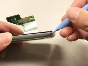
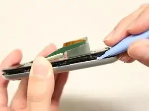
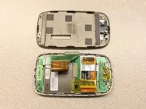
    • Insert the plastic opening tool between the front panel and the rear panel and pry open to reach the screen.

  15. tRESOrqjdO3BTWjE
    tRESOrqjdO3BTWjE
    13MTtTE2FeFC4lGD
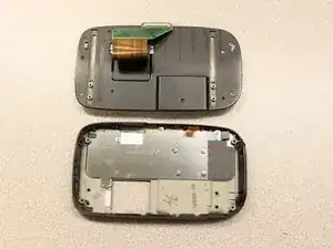
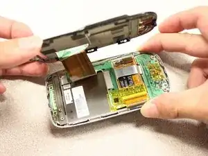
    • Once the rear panel is loose, lift it off of the front panel.

    • The flexible connection will pop loose.

  16. GoXBRvLgujHfyaxh
    • Device rotated 90 degrees CCW.

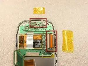
    • Remove the yellow anti-static tape.

  17. cPl1RSHrIONdhk2f
    cPl1RSHrIONdhk2f
    dHHQrYNCVG4X3IwA
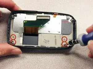
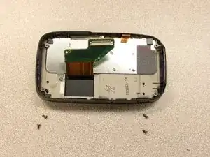
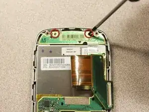
    • Unscrew the two 3mm phillips #0 screws from the bottom of the device that secure the rigid flex board to the screen panel.

  18. 3JgNB3efRPmtGnqi
    • Device rotated 180 degrees CW.

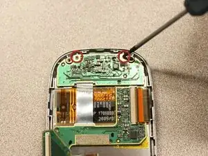
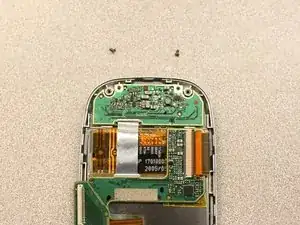
    • Unscrew the two 3mm phillips #0 screws from the top of the device that secure the rigid flex board to the screen panel.

  19. oNLUjNu1RX3KrZYo
    • Device rotated 90 degrees CCW.

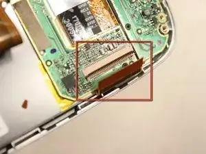
    • Unhinge the flexible connection and use the tweezers to disconnect.

  20. TLPPhheUAJ3FjaUP
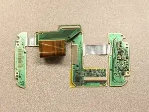
    • Now that the rigid flex board is loose, remove it from the screen.

  21. OYQYYGTFEBS2HMVM
    OYQYYGTFEBS2HMVM
    mjIRXcZuW6cDDbe4
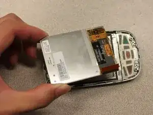
    • Simply pull out the loose screen.

  22. nnx22rrmVqSkOXEB
    nnx22rrmVqSkOXEB
    TLR4kYKqOK16kSlX
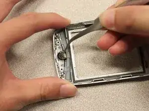
    • Use the tweezers to take out the receiver.

Abschluss

To reassemble your device, follow these instructions in reverse order.
Kyle Champ

Mitglied seit: 03/10/11

225 Reputation

0 Kommentare