Einleitung

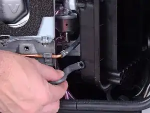
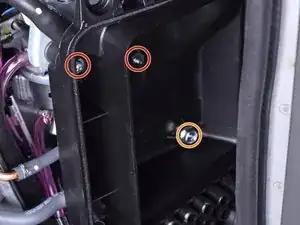
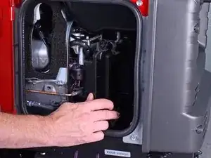
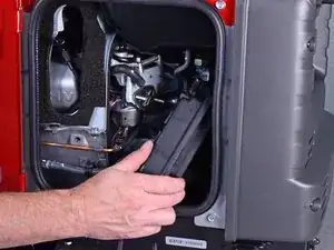
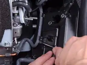
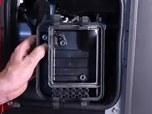
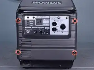
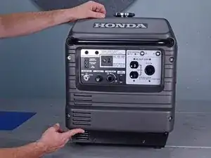
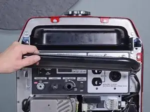
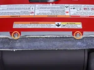
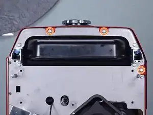
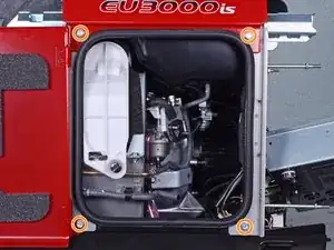
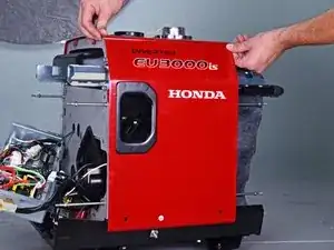
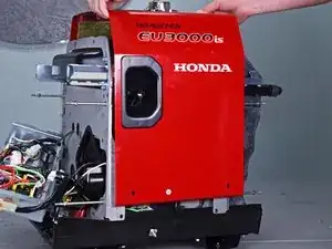
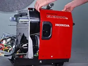
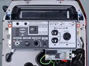
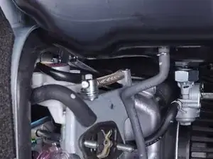
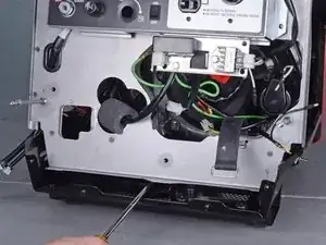
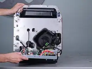
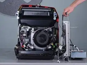
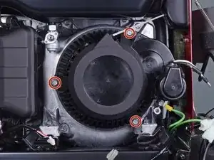
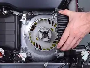
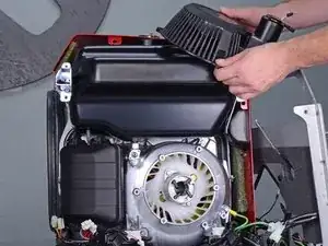
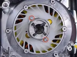
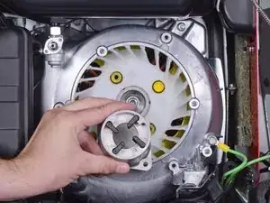
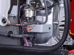
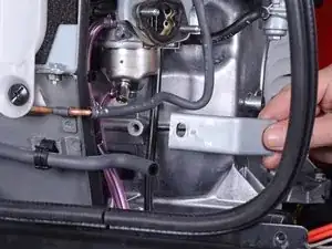
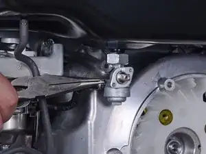
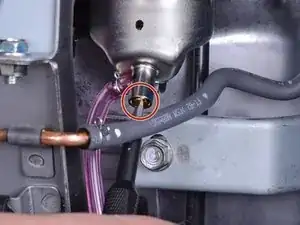
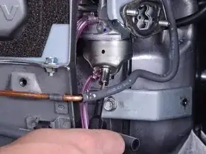
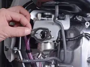
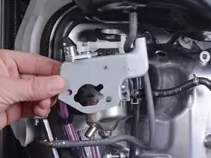
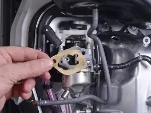
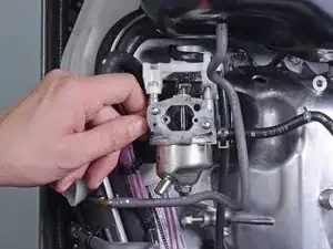
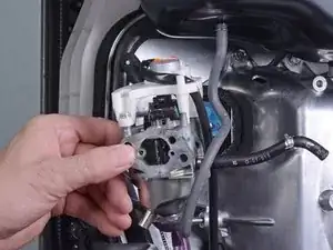
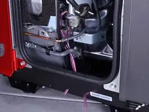
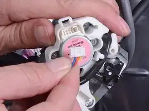
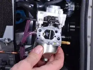
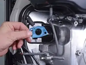
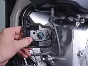
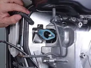
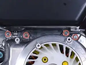
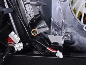
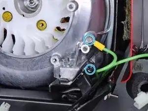
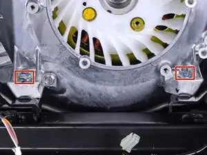
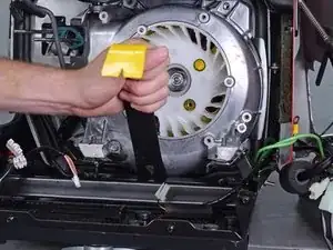
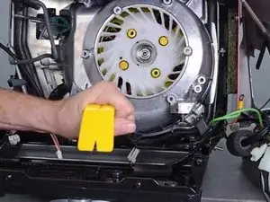
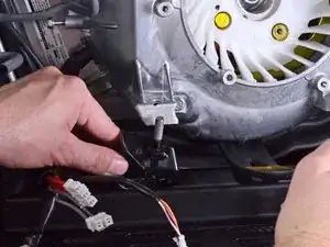
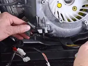
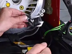
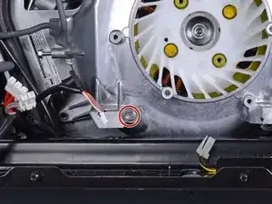
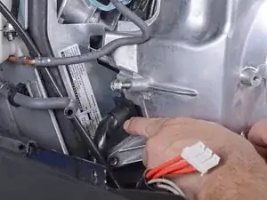
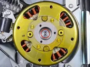
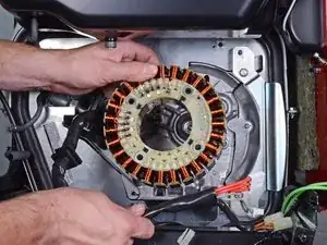
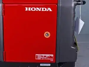
This guide shows how to remove and replace the stator for the Honda EU3000IS1AWK 3000 watt generator.

You will need the following specialty tools in order to complete this guide:

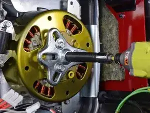
  • Flywheel puller kit with metric bolts (in order to remove the rotor)
  • Long shaft (at least 5 inches) Phillips #1 screwdriver

Be sure to drain the fuel tank before you begin this guide, and have containers at hand to catch any fuel spillage.

Some images in this guide may show minor discontinuities. They should not affect the overall guide procedure.

  1. UbGMSPUHmu5Emipg
    UbGMSPUHmu5Emipg
    EOqTsUAtCi2KFHFw
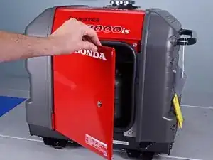
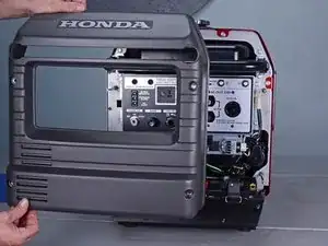
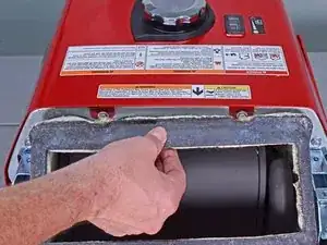
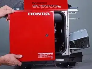
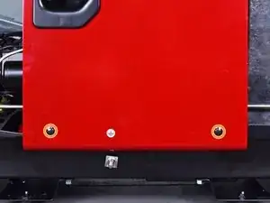
    • Before you begin, make sure the generator is off and cool to the touch.

    • Use a large flathead screwdriver to unlock the maintenance cover.

    • Open the maintenance cover.

  2. sJT2NiSJDvqIrsat
    sJT2NiSJDvqIrsat
    CGOaGS1UbALvMXom
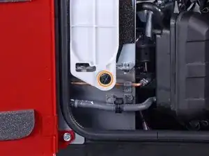
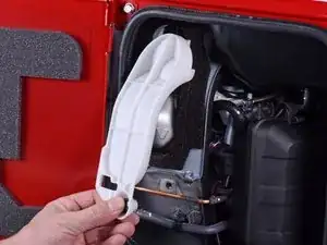
    • Use a Phillips screwdriver to remove the screw securing the spark plug cover.

    • Remove the spark plug cover.

  3. PQCWqaPkWnK4k6CD
    PQCWqaPkWnK4k6CD
    EoOtaOPaXQtnwgWu
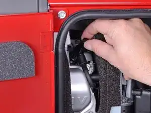
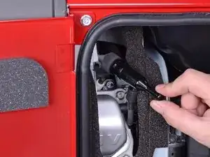
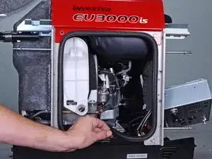
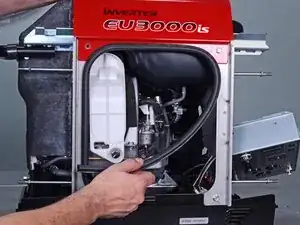
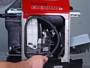
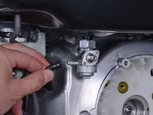
    • Grab the plastic housing at the end of the spark plug wire.

    • Pull firmly to disconnect the wire from the spark plug.

  4. 23thAcA2vMUnJWdU
    23thAcA2vMUnJWdU
    C5yxoojJaXjxcEnE
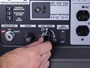
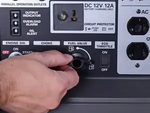
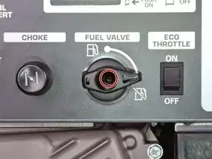
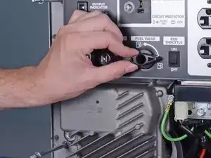
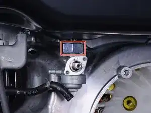
    • Turn the fuel valve to the cutoff position.

  5. ZcUKcIfj2NAhsyxd
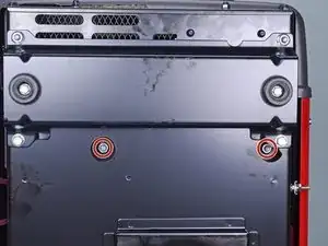
    • Carefully tilt the generator to its side or back.

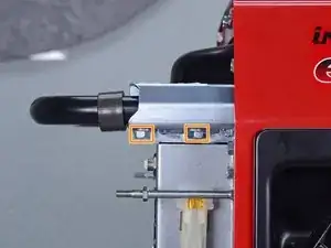
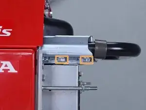
    • Use a 10 mm socket to remove the two nuts securing the front bushing mounts to the bottom of the generator.

    • Carefully tilt the generator back to an upright position.

  6. aZbFSyElfRAbk4iE
    aZbFSyElfRAbk4iE
    NSU2VO1fI6LQXpdT
    EOtddsjVDpUoDXjj
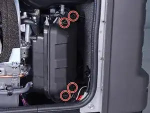
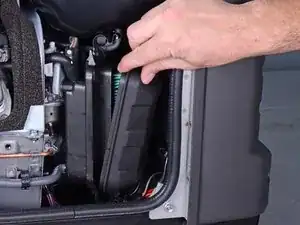
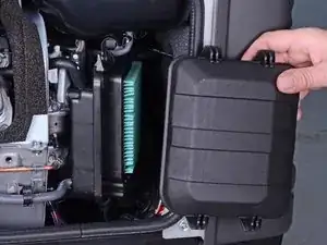
    • Unlatch the four clips securing the air cleaner cover.

    • Remove the air cleaner cover.

  7. r2CUAnagAv4TeIIJ
    r2CUAnagAv4TeIIJ
    iv6VGmToTNHLO2Qt
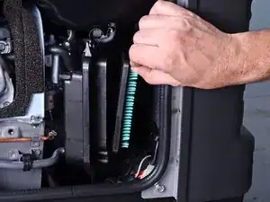
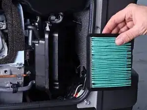
    • Remove the air cleaner filter from the housing.

  8. NRRX2WLmyXFOOINU
    NRRX2WLmyXFOOINU
    JdxoBWLsdCTrgHjb
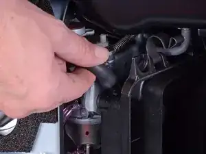
    • Pull and disconnect the breather tube from the top corner of the air cleaner housing.

  9. jJBH12ltYZQji4MO
    jJBH12ltYZQji4MO
    w6Z1feCgClIedueB
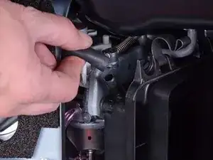
    • Pull and disconnect the lower tube from the bottom corner of the air cleaner housing.

  10. hdCBBWxetmZjJRm4
    • Use a 10 mm socket to remove the three fasteners securing the air cleaner housing:

    • Two 10 mm nuts

    • During reassembly, tighten these nuts to 6.3 ft-lb (8.5 N-m).

    • One 10 mm bolt

  11. cWHNJgHfMD4Tqrx3
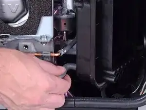
    cWHNJgHfMD4Tqrx3
    eU3IthgywBNquEqR
    • Pull the housing out slightly from its recess.

    • The housing still has tubes clipped to it.

  12. eJ6M2sUyK2YStWCk
    • Use a flathead screwdriver to pry and unclip the tube from the air cleaner housing.

  13. mWKqHEQm5p2O4Qc5
    • Remove the air cleaner housing.

  14. iDvNAmrIrrmIpxK6
    iDvNAmrIrrmIpxK6
    P6XwTuMvPDD4ye2E
    F4Ipy2BmDPGU5Ebk
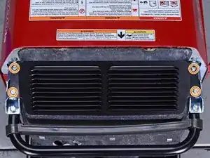
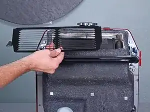
    • Use a 10 mm socket to remove the four capped nuts securing the front cover.

    • Remove the front cover.

  15. 1DRBwHgTRILgyWjD
    1DRBwHgTRILgyWjD
    ZKyFe25Z4625G2N2
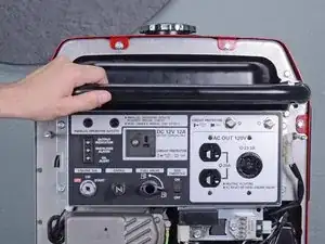
    • Use a 10 mm socket to remove the four bolts securing the handle to the frame.

  16. VZhXdEESKXwDxZfP
    VZhXdEESKXwDxZfP
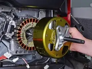
    KeSXV4LVjmwZvQ4q
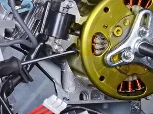
    • Remove the handle.

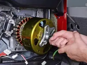
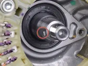
  17. B4mZdaK3yv6sOwTA
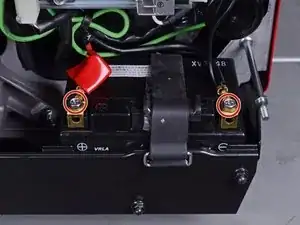
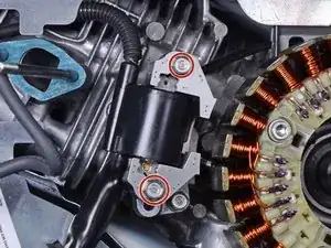
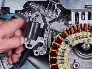
    • Use an 8 mm socket to disconnect the battery wires from the battery terminals.

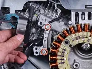
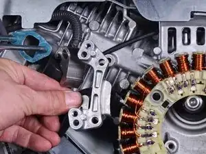
    • Disconnect the black negative cable first to prevent the risk of shorting the battery.

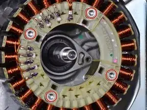
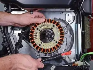
    • During reassembly, connect the black negative cable first. Make sure you reconnect the wires in the correct polarity.

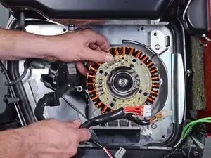
  18. Rtd2gVSNJQMZfDER
    Rtd2gVSNJQMZfDER
    2VUsPrTZH6UGGAHL
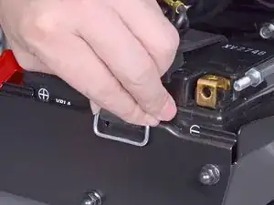
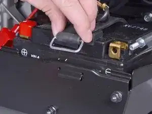
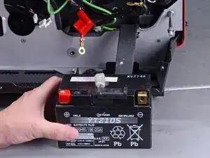
    • Unclip the battery strap from the lower plate.

  19. JUpfTWDkcOFirXJP
    • Remove the battery.

  20. RDZUVKlwTMFoDWqW
    RDZUVKlwTMFoDWqW
    r4IFmRkNHWogk3sr
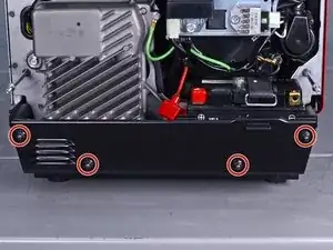
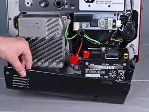
    • Use a 10 mm socket to remove the four capped nuts securing the lower plate.

    • Set these capped nuts apart. They look similar, but are smaller than the front cover nuts.

    • Remove the lower plate.

  21. bsIFORL3CwVedQRS
    bsIFORL3CwVedQRS
    SkSZvRQJ3uLuFixC
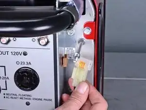
    • Insert a flathead screwdriver into the top of the brown fuse clip in order to release the fuse holder.

    • Detach the fuse holder from the brown clip.

  22. QuHfgHuEQ4VthYnL
    QuHfgHuEQ4VthYnL
    QXdqRVvHKZyuPUNu
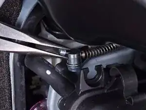
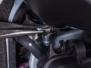
    • Use pliers to lift and disconnect the choke cable from the choke stay.

    • During reassembly, be sure to test the choke to ensure that it is properly connected.

  23. Kr1wUlNnspfySpYL
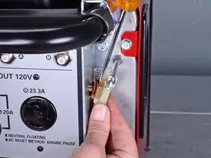
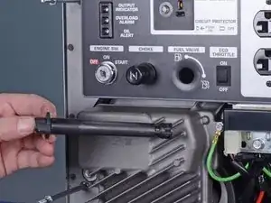
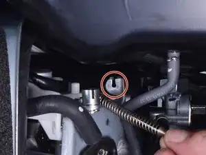
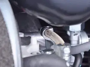
    • Use a long shaft Phillips screwdriver to remove the deeply recessed screw securing the fuel cutoff switch.

    • Be careful not to turn the fuel cutoff switch while you remove the screw.

  24. WxlUVQ2yhw2BNXyB
    WxlUVQ2yhw2BNXyB
    1dkhrTXLElKMKoaR
    • Remove the fuel cutoff switch.

    • During reassembly, be sure to test the switch to ensure that it is properly installed.

  25. RLiROE5UcjRcT6LM
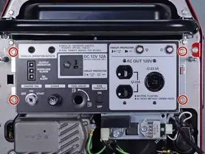
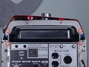
    • Use a 10 mm socket to remove the four bolts securing the control panel.

  26. 2BWAAS6wDiR1qRHQ
    2BWAAS6wDiR1qRHQ
    ToGduqcQLsj2TYUY
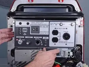
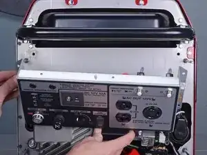
    • Carefully tilt the control panel downwards.

    • The control panel will still be connected to many wires and cables. Be careful not to strain any of the connected wires.

  27. yisIoCCa4EQOvp4f
    yisIoCCa4EQOvp4f
    5AWchIdoWZJSdff5
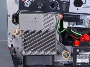
    • Remove the following bolts securing the inverter:

    • One 8 mm ground bolt

    • Three 10 mm bolts (one behind the control panel)

  28. XhIjcjWBGTa1DoD2
    XhIjcjWBGTa1DoD2
    DRNHXClo6UvsENDZ
    ZqiNgEEOEqirHYd2
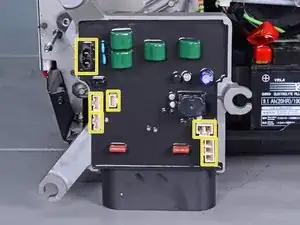
    • Reach behind the inverter along the edges and disconnect the six connectors from the back of the inverter.

    • All the connectors use locking tabs, so you will have to squeeze them in order to release them.

    • The third image shows the locations of all six sockets on the inverter.

    • Reassembly tip: Every socket on the inverter is different, so you can't plug something into the wrong place. Do not force the connectors into their sockets.

  29. KXJh6hti66cTXpwL
    KXJh6hti66cTXpwL
    kxbSKsNJr5IAcah5
    • Remove the inverter.

  30. 5hFMIbRljs3bKVaC
    5hFMIbRljs3bKVaC
    WfYTfi4RVX2vEJLM
    • If you are replacing the inverter and the replacement did not come with rubber mounts, follow the next two steps to transfer them over.

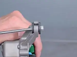
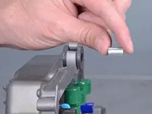
    • Use a screwdriver to push the metal collar out of the center of the rubber mount.

  31. RUUJZ23DwxTcyEyh
    RUUJZ23DwxTcyEyh
    OLMHZcWsYnYJbDgp
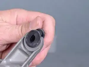
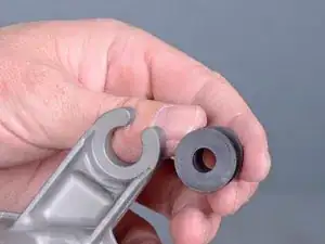
    • Squeeze the mount and remove it from the inverter.

    • Repeat the procedure with the remaining mounts and transfer them to the replacement inverter.

  32. P14vVRKyroUSmZFs
    P14vVRKyroUSmZFs
    ADvRsCDgUgXIYcUA
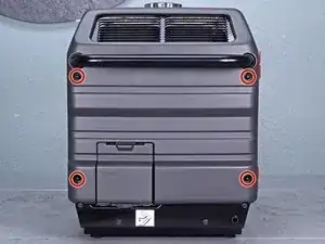
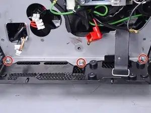
    • Use a 10 mm socket to remove the four capped nuts securing the rear cover.

    • Remove the rear cover.

  33. MtEuK6VfG1fGEPUw
    MtEuK6VfG1fGEPUw
    MwB1gIMYGNHEXMPk
    • Use a 10 mm socket to remove the four bolts securing the muffler protector.

    • Remove the muffler protector.

  34. NhpjJD4A4KNyd6EG
    NhpjJD4A4KNyd6EG
    fQS5kMgywOLI6awU
    • Pull the muffler shroud slightly away from the frame to access the top frame bolts.

    • Use a 10 mm socket to remove the two bolts securing the top edge of the cover.

  35. iPYdklTClSWnBbFf
    • Use a 10 mm socket to remove the three bolts securing the front edge of the cover.

  36. kPDhbCcPSv1StlbJ
    kPDhbCcPSv1StlbJ
    QBiFnQU6DTsSK3tw
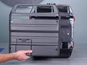
    • Use a 10 mm socket to remove the four bolts from the maintenance cover side.

    • Remove the maintenance cover.

  37. Ok6jIcrLxo22NxWi
    Ok6jIcrLxo22NxWi
    yHVOOOhVppH6EHUX
    Iufj2BlxswtjmDDc
    • Carefully peel the maintenance cover seal from the frame.

  38. rHPRHkcOk4tIZgU3
    • Use an 8 mm socket to remove the two bolts securing the non-access side of the cover.

  39. fgAVvIST5hfIFbUN
    fgAVvIST5hfIFbUN
    RZAw66X1K2msEnOR
    • Unscrew the gas cap.

  40. eeci2JiEUI32YB4j
    eeci2JiEUI32YB4j
    diBtGR1vkfaOQPWB
    ZOfZWBNXQarvZg4U
    • Lift the cover up slightly to free it from the frame and slide it back by a few inches.

  41. wOJX5VyZUcPWeSr6
    • At this point, it may be helpful to temporarily re-attach the control panel back onto the front frame with some 10 mm bolts.

  42. Sy5ZVnsH15SDY1RM
    Sy5ZVnsH15SDY1RM
    F6PL2cCqmEOpNCcU
    vuQscjMG6Hlc5UO6
    • Lift up and release the choke cable's rubber bushing from the choke stay.

    • During reassembly, make sure that the choke cable's rubber bushing is properly seated on the choke stay.

  43. 5i1SiyN6ljHpcQu2
    • Use a 10 mm socket to remove the three frame bolts securing the bottom of the front frame.

  44. lFlEYTbfAnhH1s2P
    • Use a 10 mm socket to remove the four bolts securing the top of the front frame.

  45. cXAXYPWHFIWDovGB
    cXAXYPWHFIWDovGB
    XAjbDjhlsTyiFYem
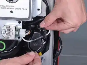
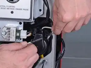
    • Pull and disconnect the starter motor's black barrel and white barrel connectors.

    • During reassembly, the wires should be reconnected to their respective colors.

  46. bjkNYBpo2EtAOOAM
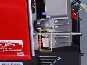
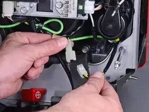
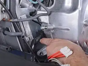
    • Unplug the two-wire oil switch connector.

  47. 4BxeWihLRZhPXKoB
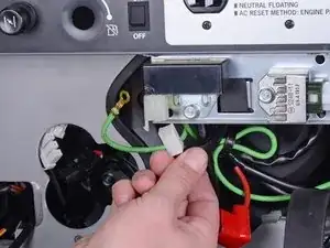
    • Unplug the four-wire regulator connector from the bottom edge of the control panel.

  48. tIlEJeeEgSB3IWNP
    tIlEJeeEgSB3IWNP
    LdDt5gASCHjuJRwy
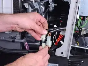
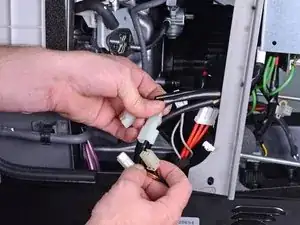
    • Unplug the two winding connectors.

    • These connectors all have brown wiring in black sleeves.

  49. gplsTffxSI4aIfXa
    gplsTffxSI4aIfXa
    fo63ZKuYHMDQndyq
    KOYtCPy2iX21HA22
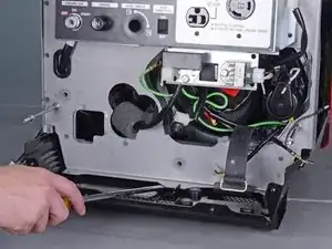
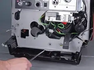
    • Insert the edge of a large flathead screwdriver under the bottom edge of the front frame.

    • Pry up and outward to release the bottom edge of the front frame.

  50. FItjwbodFYTYW6jY
    FItjwbodFYTYW6jY
    VcsEmo6L3TIMLDDp
    • Carefully swing the front frame to the right side of the generator.

    • While the images show the control panel unbolted from the front frame, you can keep it bolted to the frame.

    • The front frame is still connected to the generator by many wires. Be careful not to strain any wires.

  51. Nx4cRTfMqjwGRfER
    • Use a 10 mm socket to remove the three bolts securing the recoil starter.

  52. bvSbn52YuSqTjcpM
    bvSbn52YuSqTjcpM
    OdCZWKYeRoHTLWdG
    dYZGvRfH6vaZLmVB
    • Remove the recoil starter and move it out of the way.

    • Be careful not to lose the metal collar in each of the recoil starter's bolt holes.

  53. 2EPvhZTZgZhNTObH
    2EPvhZTZgZhNTObH
    uFlUAnpUTnFiWpKe
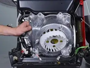
    • Use a 10 mm socket to remove the two bolts securing the starter pulley.

    • Remove the starter pulley.

  54. GH1LSv6AUGlebUMr
    GH1LSv6AUGlebUMr
    kRyQDJGHPnsNZXjB
    • Use a 10 mm socket to remove the bolt securing the air cleaner housing bracket.

    • Remove the air cleaner housing bracket.

  55. iafrwOYVRZyEbsWA
    iafrwOYVRZyEbsWA
    xJEVkkIgsujiSbhp
    • Fuel may leak out when you disconnect this hose. Be ready to catch any spillage.

    • Use pliers to squeeze and loosen the hose clamp securing the carburetor fuel line.

    • Pull and disconnect the carburetor fuel line from the petcock assembly.

  56. cZhWRIyIrbTRqfOS
    cZhWRIyIrbTRqfOS
    UAuos6jk2oV4YAtl
    • Be sure to drain the fuel tank before you perform this step.

    • Use a large crescent wrench to loosen the petcock assembly from the fuel tank.

    • Residual fuel will leak out as you remove the petcock assembly. Be ready to catch any spillage.

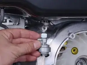
    • Remove the petcock assembly.

  57. A4bqPOFtS1CLPqIV
    A4bqPOFtS1CLPqIV
    KGeOAPMb4nDF1WpY
    VCDqxGDcGAfAtxcg
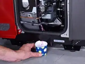
    • Place a container below the carburetor drain tube to catch the excess fuel.

    • The carburetor drain screw is located at the bottom of the carburetor.

    • Use a flathead screwdriver to loosen the brass fuel drain screw until fuel begins to drain out of the carburetor.

    • Once you drain the fuel bowl, re-tighten the fuel drain screw.

  58. VBbgNfAw3DD4cpFO
  59. xEAVtffVDXaOUb1u
    • Remove the choke stay.

  60. FUYSBUIUpOluOI1r
  61. Bx4nGSlfsf2LUXkd
    Bx4nGSlfsf2LUXkd
    cMyuGxJbpTNqb3iI
    bSxtk52K4dZQKxsY
    • Slide the carburetor off the mounting bolts.

    • During reassembly, use the third photo as a reference for how to route the carburetor tubes.

  62. RPRejsbimxG5Cx2R
    • Disconnect the throttle control connector from the top of the carburetor.

    • Unwrap the throttle control wires from the carburetor.

  63. XpoYGb5n24ZJMdnU
    • Remove the carburetor.

  64. YiDfAWdtc6jCjSeh
  65. kkmyCvmuCpoj5ioK
    • Remove the carburetor insulator.

  66. onEcuj3blGef1sU3
  67. KHB5EGLVBuQCaFP5
    KHB5EGLVBuQCaFP5
    NUGUPZ6PdGdo4NUC
    xiuKSDKcXXPRKRYv
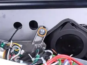
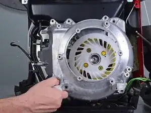
    • Use a 10 mm socket to remove the seven bolts securing the fan cover:

    • Four bolts on top

    • One recessed bolt in the bottom left corner

    • Two bolts in the bottom right corner

    • During reassembly, be sure to reattach the ground wire.

  68. DUhyuAQPWdcrer1W
    • Use a 12 mm socket to remove the mounting nuts securing the front bushings.

  69. 42EcW26uH6ZFibjJ
    42EcW26uH6ZFibjJ
    m4PvDqbdKFLkAIKw
    • Insert a pry bar underneath the fan cover.

    • Pry upwards to lift the generator assembly slightly.

  70. AmIUdUJZDdONlhvG
    AmIUdUJZDdONlhvG
    Stcyxf2KAWII1Z21
    OUkYw2OqhsZGGo1t
    • As you lift the generator assembly with the pry bar, maneuver and remove the two generator mounts from their recess.

  71. uUFDp32n4diZtSC1
    • Use a 10 mm socket to remove the long bolt from the fan cover.

  72. nZiItkS33O1kR6mk
    nZiItkS33O1kR6mk
    SiMFYYtRUBUJB25K
    • Carefully pull the fan cover away from the generator assembly.

    • During reassembly, make sure that the cord grommet is properly slotted into the fan cover.

  73. dUuayvmEWMXtNiDf
    dUuayvmEWMXtNiDf
    3V4LX3yDgevxR1OJ
    • The fan cover is a tight fit. You may need to push the gas tank upwards as you maneuver the fan cover out.

    • Remove the fan cover.

  74. HKc4MjHrAorCE2jP
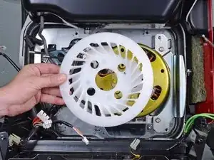
    • Remove the cooling fan.

  75. u2cJ4HTTwXPQKAXq
    • Use a 19 mm socket to remove the nut securing the rotor to the generator shaft.

    • During reassembly, tighten this nut to 55 ft-lb (74 N-m).

  76. Vh3aypvEETw4sTbi
    Vh3aypvEETw4sTbi
    CXNHYwqahDXQiH1h
    • Attach a flywheel puller to the rotor and use it to loosen the rotor.

    • To prevent the rotor from spinning, insert a flathead screwdriver into one of the rotor slots and brace it against the ignition coil bracket.

    • Be careful not to insert the screwdriver too deeply into the slot, or you will damage the stator.

  77. wAJkStBbYtx5FlVO
    wAJkStBbYtx5FlVO
    ng6qFiJFAA3XtYHI
    RSPsAUVl5uIZKDmq
    • Remove the rotor.

    • Be careful not to lose the Woodruff key.

    • During reassembly, be sure to align the rotor to the Woodruff key.

    • After you install the replacement rotor, rotate it by hand to make sure that the rotor does not rub against the stator.

  78. U6n1ywYsOXQNRVR1
    U6n1ywYsOXQNRVR1
    1oID2NqeBGWEQWYh
    • Use a 10 mm socket to remove the two bolts securing the ignition coil.

    • Loosen the ignition coil from the frame.

  79. VdCkRdMpAFOLGpwX
    VdCkRdMpAFOLGpwX
    IojOUPv2Vx2hwVPQ
    • Use a 10 mm socket to remove the two bolts securing the ignition coil bracket.

    • Remove the ignition coil bracket.

  80. QPrWBkftNMNgfotb
    • Use a 4 mm hex key to remove the four bolts securing the stator.

    • During reassembly, tighten these bolts to 8 lb-ft (11 N-m).

  81. MnSlyvEwLSV5dO3g
    MnSlyvEwLSV5dO3g
    GdLoI3AKHAFcVUYa
    • Remove the stator.

Abschluss

To reassemble your device, follow these instructions in reverse order.

Arthur Shi

Mitglied seit: 03/01/18

218620 Reputation

2 Kommentare

Hy How Are You

I Have Many Time Open EU30is or Eu65is . Thanks For Sharing in Picture Wire Every Steps. I Had Not Agree Your Step, No 76.

Step No.76 (Be careful not to insert the screwdriver too deeply into the slot, or you will damage the stator.)

Not Agree, Please Use Fly Wheel Stoper Holder. or Special Tool, Thank You.

Allah Blessings You.

asif basheer -

I too think step 76 is a recipe for destroying the flywheel. The shock and distortion of using a flywheel puller in this manner will cause the magnets to break away from the flywheel. Instead undo the flywheel bolt a few turns and use a thick bar of metal with 7mm holes to coincide with the recoil cup holes in the flywheel. Use bolts through the bar into the threaded m6 recoil cup holes in the flywheel to put a bit of pressure on the flywheel nut with the bar. Then tap the bar sharply with a hammer above the flywheel nut. The flywheel will disengage easily. While doing this be careful that the bolts do not go far enough into the flywheel to damage the windings. You should be able to align the threaded holes with the heads of the bolts holding the stator to protect against this possibility.
Donchampignon -