Einleitung

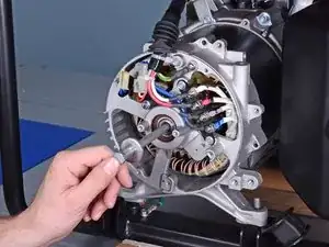
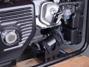
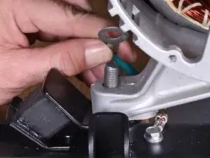
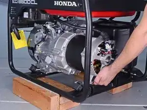
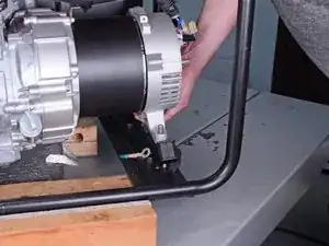
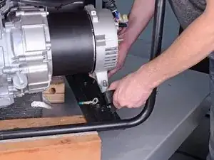
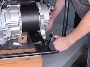
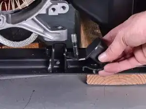
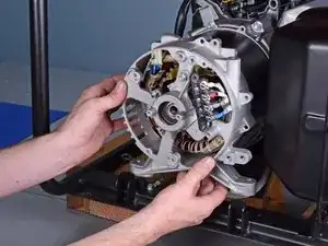
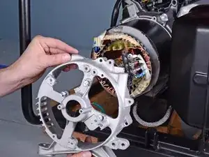
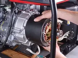
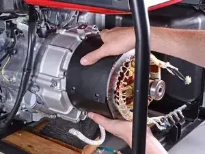
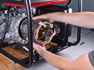
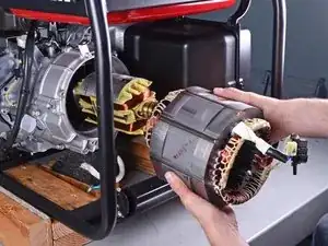
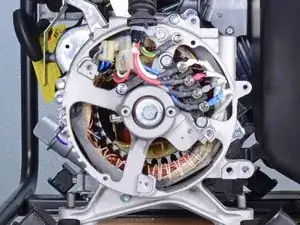
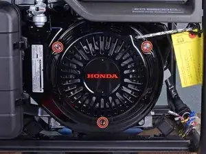
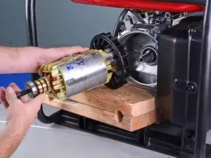
This guide shows how to remove and replace the rotor for the Honda 6500 Watt Generator EG6500CL AT.

Warning: You need a Honda rotor puller tool (07HPC-ZC2010A or 07HPC-ZC2010B) in order to complete this procedure. You will not be able to remove the rotor without this tool.

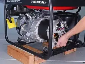
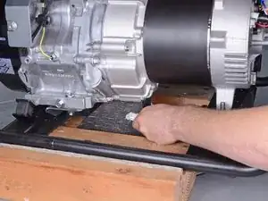
This procedure shows how to complete the procedure without removing the generator from the frame.

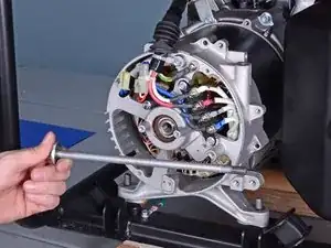
You will need some wooden blocks between 2-4 inches thick to support the generator and rotor. You will also need a metal rod or extra large screwdriver in order to brace and lock up the generator axle.

  1. DmxWmIMhwA22AFBe
    DmxWmIMhwA22AFBe
    XBJ2c5RKBUW5ea1u
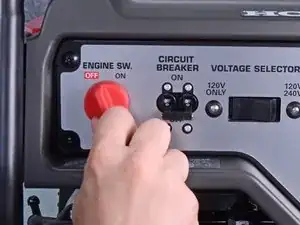
    • Before you work on the device, make sure to switch the engine off.

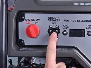
    • Switch the circuit breaker off.

  2. FdF22f2xXhCGrGpE
    FdF22f2xXhCGrGpE
    AG6kDCtri5JHyGkh
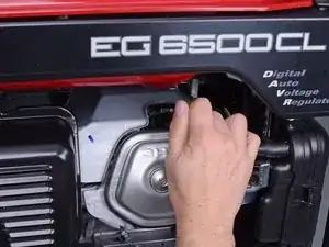
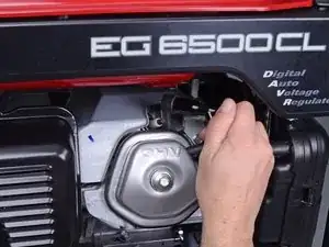
    • Grab the plastic housing at the end of the spark plug wire.

    • Pull firmly to disconnect the wire from the spark plug.

  3. S1gJ5ahkvBXNmtZD
    S1gJ5ahkvBXNmtZD
    g6SVhTiJQDAQj3Dt
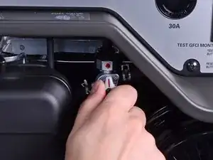
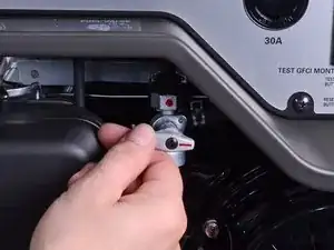
    • Twist the fuel valve clockwise into the cutoff position.

  4. etQSbfRFh1Yjq4N3
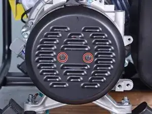
    • Use a Phillips screwdriver to remove the two screws securing the generator cover.

  5. TYqGfUcnjb2tinLw
    TYqGfUcnjb2tinLw
    Fcer6BLwJKyuuXUQ
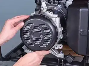
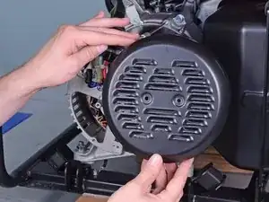
    • Remove the generator cover.

  6. EslJgotqXgYl5Pbt
    EslJgotqXgYl5Pbt
    RH3K6NiBjQMlOA5J
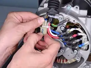
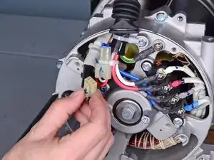
    • Squeeze and disconnect the stator connector from the wiring harness.

  7. NXwHxa4LmKqJAqlT
    NXwHxa4LmKqJAqlT
    thXBiVEuTh32KwjG
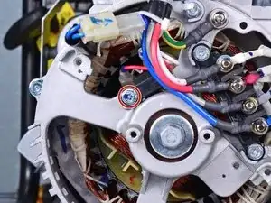
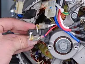
    • Use a 10 mm socket to remove the bolt securing the brush assembly.

    • Pull the brush assembly out slightly from its recess.

  8. I2kHrJTyZXb3eWWN
    I2kHrJTyZXb3eWWN
    im6HqylmG5YlOMX2
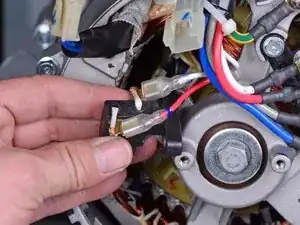
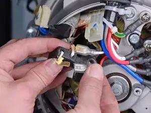
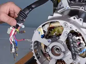
    • Disconnect the two spade connectors from the brush assembly.

  9. UumErbFwi6qahfV3
    UumErbFwi6qahfV3
    xVpVFMwYhEIkDvLP
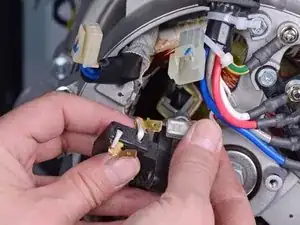
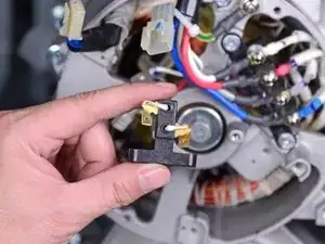
    • Remove the brush assembly.

    • During reassembly, use the second photo as reference for how to wire the brush assembly.

  10. apIUM4RjDYNxlnCU
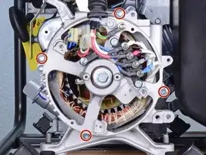
    • Use a 10 mm socket to remove the four long bolts securing the generator cover to the generator assembly.

    • During reassembly, tighten these bolts to 7 ft-lb (10 N-m).

  11. IItZ3f4ZeeeIN3gi
    IItZ3f4ZeeeIN3gi
    FslLtFA52BDVIhhY
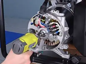
    • Use a 14 mm socket to remove the rotor bolt from the generator assembly.

    • This bolt may be difficult to loosen. If you have trouble removing the bolt, use an impact wrench or breaker bar.

    • During reassembly, tighten this bolt to 33 ft-lb (44 N-m).

  12. SQTCdlQ2ZsYcTLtX
    SQTCdlQ2ZsYcTLtX
    DBobmx5fZ5q5Tn3P
    • Remove the rotor bolt and washer.

  13. 1hFOEvhUPjKpWYvm
    1hFOEvhUPjKpWYvm
    ks3IgmRJeavBbLpm
    HSZl5ISy1YuIjhQ2
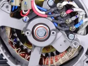
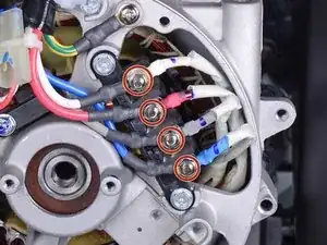
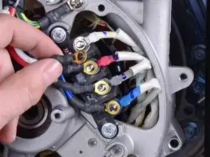
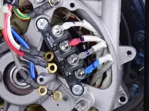
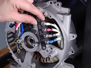
    • Use an 8 mm socket to remove the four nuts securing the wiring harness to the terminal.

    • Remove only the top nut from each terminal post.

    • Be careful not to lose the crush washers behind them.

    • Remove the wiring harness wires from the terminal.

  14. aKOlJdtlTGO6KKNL
    aKOlJdtlTGO6KKNL
    UolChACEWyci4HEy
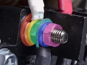
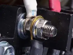
    • During reassembly, use these photos as a reference for how to re-stack the terminal posts. From the terminal base to tip:

    • Base washer

    • Crush washer

    • Stator wire connector

    • Nut

    • Wiring harness connector

    • Crush washer

    • Nut

  15. n5lYqCHAMA6KPl6y
    n5lYqCHAMA6KPl6y
    FByo3RhUM2iiNPUq
    iYYvlQVHhmNuTqCG
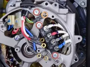
    • Use an 8 mm socket to remove the three bolts securing the wiring terminal and harness.

    • Remove the Phillips screw securing the harness ground.

    • Loosen the wiring terminal and harness from their resting positions.

  16. iUlQuyHDZoOr1sYv
    iUlQuyHDZoOr1sYv
    yVXXI5dqCiUMXtWB
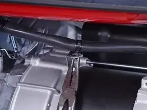
    • Use pliers to release the cable tie securing the wiring harness to the generator assembly.

  17. GxrGRg3MMTYY1ja2
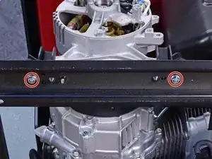
    • Carefully tilt the rear of the generator upwards to access the under-frame bolts.

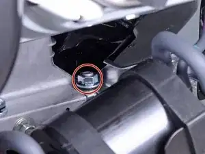
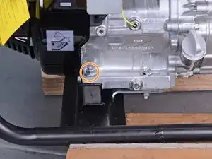
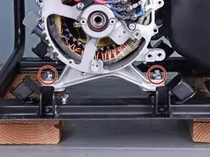
    • Use a 12 mm socket to remove the two bolts underneath the frame, which secures the rear generator housing.

  18. UElrFZdCRPRDI2kO
    UElrFZdCRPRDI2kO
    DtbN2SSjWwlNONfx
    QLPZFoPv2FdTsBZb
    • Removing these nuts give the generator assembly enough slack to remove the rear bushings.

    • Use a 14 mm socket to remove the mounting nut next to the emissions canister.

    • Use a 14 mm socket to remove the mounting nut near the oil filler hole.

  19. utcDXZpWTHxQU3MU
    utcDXZpWTHxQU3MU
    kyTLmWccP6QPiOTj
    • Use a 14 mm socket to remove the two nuts securing the rear housing to the bushings.

    • During reassembly, be sure to re-attach the ground terminal to the left bushing.

  20. hdTK5vcLLFoJBWv6
    hdTK5vcLLFoJBWv6
    bUwyMEGoepgERk1l
    AfefeXmcJY2xUqP3
    • In these photos, the generator frame is propped on some blocks for ease of access. You do not need to do this for the procedure.

    • Tilt the generator assembly by lifting the rear housing slightly.

    • Place support blocks underneath the silver generator housing to support the generator assembly.

    • The generator weight should rest on the support blocks and no longer on the rear bushings.

    • Do not support the generator by the black stator cover.

  21. 6rURHKePRixQafYv
    6rURHKePRixQafYv
    cOrJS6oxiEX6OllA
    VQo4LnsBBslAyokD
    • Lift the rear generator housing up as far as you can and maneuver the left bushing out of its socket.

    • Remove the left bushing.

  22. 5fQRM1Hg4xhX1nt6
    • Repeat the previous step to remove the right bushing from its socket.

  23. lbJO1HKQAyxtNfcx
    lbJO1HKQAyxtNfcx
    4XL2DsaMU1vgEcSQ
    • Remove the rear generator housing from the generator assembly.

  24. xSjTZsSivLCCoUwW
    xSjTZsSivLCCoUwW
    xUEvpYK46IjwXcXu
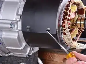
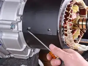
    • Rotate the stator cover so that the seam is at an accessible angle.

  25. d2XNUfGpDXn61sRk
    d2XNUfGpDXn61sRk
    TxF5dsYOfwdtA6FH
    mWHqiGfA3AX2aYda
    • Use a flathead screwdriver to pry up the tabs holding the stator cover together.

  26. M6Pa5g6RMBrXOFSM
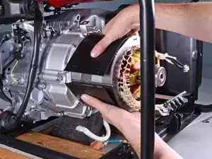
    • Remove the stator cover.

  27. hBw2XLDH5iUenGLP
    hBw2XLDH5iUenGLP
    LFJ1BtyMLAEPxnoI
    YBoxOFByqFZGnRpQ
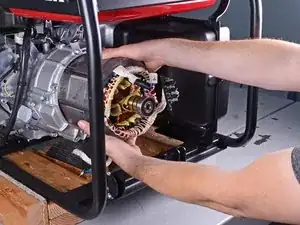
    • Remove the stator by pulling it straight out of the generator assembly.

  28. Rv61TTNbhfMjJmxa
    • During reassembly, you don't need to install the stator in a precise rotational position. Just make sure the stator cables wires are in the top-left corner.

  29. PNG3nsLCM2T3y3Jk
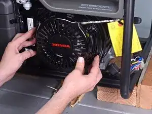
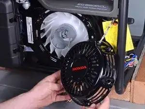
    • Use a 10 mm socket to remove the three bolts securing the recoil starter.

  30. HQsZwNJUsCjKgRDL
    HQsZwNJUsCjKgRDL
    nZaxlESuIRqdI1H4
    • Remove the recoil starter.

  31. KM4PdrhcrWXoZSKs
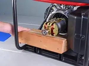
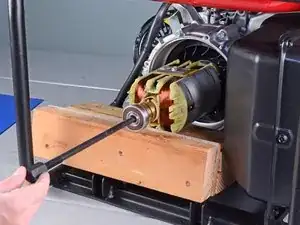
    • Place wooden blocks under the flat side of the rotor to prevent it from rotating.

  32. qTUygGmEMjYGk6jm
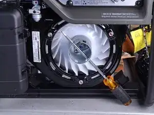
    • Insert a metal rod or a large screwdriver through the starter pulley to lock the rotor axle in place.

  33. 5CLYZlT6rGXMX4qV
    5CLYZlT6rGXMX4qV
    LFYCaMXSLTIkQXmE
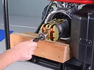
    • Insert the rotor puller tool into the rotor axle.

    • Hand-tighten the puller tool onto the rotor threads.

  34. BVx4MSDEwOgGXXAj
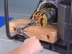
    • Use a 19 mm socket to tighten the puller tool until it breaks the rotor free from the generator assembly.

    • If you have trouble freeing the rotor, use a breaker bar to tighten the puller tool.

  35. gTclQyspGx5QPws2
    gTclQyspGx5QPws2
    1QHKALCZbrqxLHoe
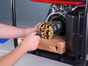
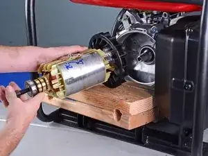
    • Remove the rotor.

  36. eZkNCtYJKidMBMur
    eZkNCtYJKidMBMur
    CrBI36DaaZ5JObhs
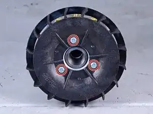
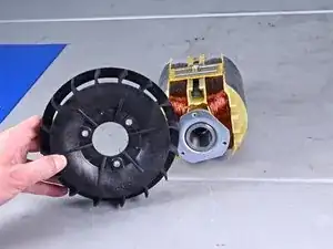
    • Use an 8 mm socket to remove the three bolts securing the rotor fan.

    • Transfer the fan to your replacement rotor.

  37. pDPPX2lZ1QDffo6K
    pDPPX2lZ1QDffo6K
    E24odHyripeIy1ST
    • The next three steps show how to align and re-attach the rotor back onto the generator assembly.

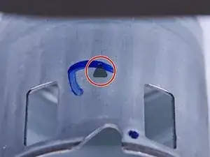
    • Rotate the starter pulley until the top-dead-center marker is facing straight up.

    • The top-dead-center marker is a faint triangular indent on the starter pulley.

    • Once aligned, do not rotate the starter pulley or drive shaft until you've attached the rotor.

  38. aL1aWFQLWWX1mhNb
    aL1aWFQLWWX1mhNb
    BB1BUV5BMDpQr6HG
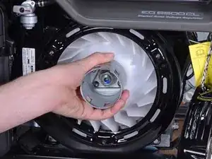
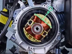
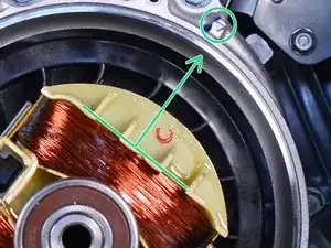
    • Align the rotor such that the flat side of a rotor coil sits perpendicular to the alignment arrow at the top-right edge of the generator case.

    • You don't have to align the rotor precisely—it just needs to be in the general direction as shown.

  39. ipd2LUNHpKrlaAFT
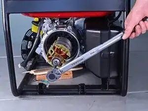
    • Insert the rotor bolt and washer into the rotor axle.

    • Use a 14 mm socket and torque wrench to tighten the rotor bolt to 33 ft-lb (44 N-m).

    • Reassemble the rest of the generator by following the instructions in reverse.

Abschluss

To reassemble your device, follow these instructions in reverse order.
Arthur Shi

Mitglied seit: 03/01/18

218620 Reputation

0 Kommentare