Einleitung
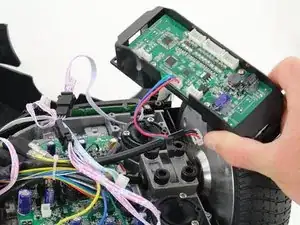
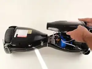
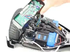
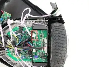
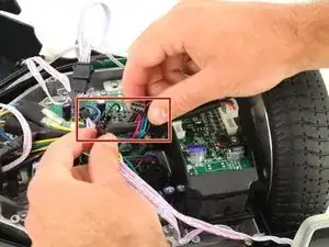
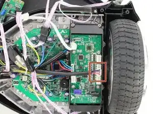
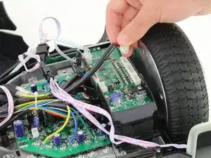
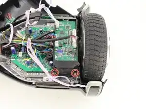
This guide explains how to remove the sensor assembly for your Hover-1 H1 hover board.
Werkzeuge
-
-
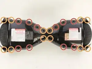
Remove the ten 9mm machine screws by using a long Phillips #2 screwdriver to rotate the screws counterclockwise.
-
Remove the twelve 9mm sheet metal screws by using a long Phillips #2 screwdriver to rotate the screws counterclockwise.
-
-
-
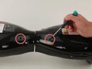
Puncture the two black stickers by using the tip of a screwdriver.
-
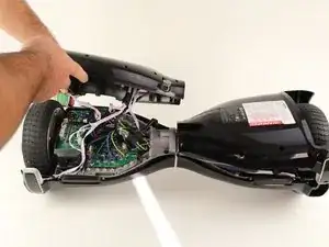
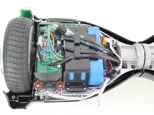
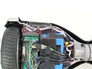
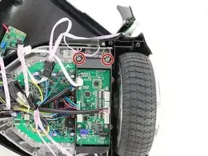
Remove the two 9mm machine screws by using a long Phillips #2 screwdriver to rotate the screws counterclockwise.
-
-
-
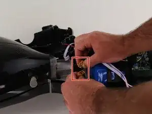
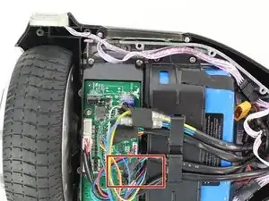
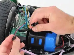
On the battery side of the hoverboard, remove the red, black, and purple sleeved cable from the sensor assembly by squeezing the tab and pulling up.
-
-
-
Remove the red, blue, and green cable from the cable extension connected to the sensor assembly by squeezing the tabs on the side of the connector.
-
-
-
Remove the four 7mm screws by using a Phillips #2 screwdriver to rotate the screws counterclockwise.
-
-
-
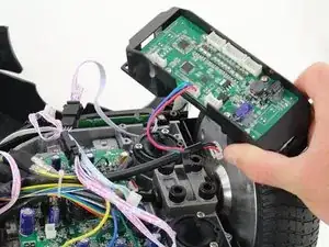
Remove the sensor assembly on the battery side of the hoverboard by gently lifting and pulling away from the hoverboard.
-
-
-
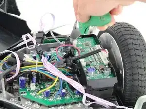
Remove the hot glue holding in the connectors with a utility knife.
-
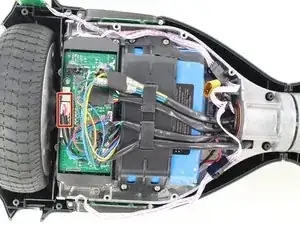
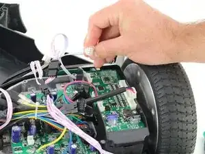
Remove the white cable from the sensor assembly by squeezing the connector and pulling the connector up.
-
-
-
Remove the red, blue, and green cable from the extension connected to the sensor assembly by squeezing the tabs on the side of the connector.
-
-
-
Remove the red and black sleeved connector from the sensor assembly by squeezing the tab and pulling up.
-
-
-
Remove the four 7mm screws by using a Phillips #2 screwdriver to rotate the screws counterclockwise.
-
-
-
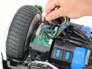
Remove the sensor assembly on the motherboard side of the hoverboard by gently lifting and pulling away from the hoverboard.
-
To reassemble your device, follow these instructions in reverse order.
