Einleitung

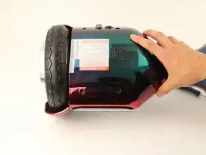
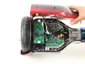
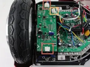
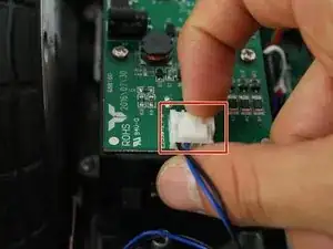
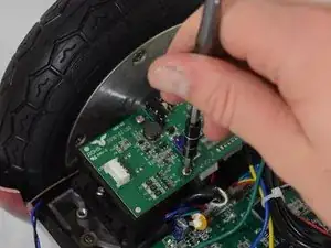
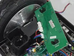
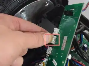
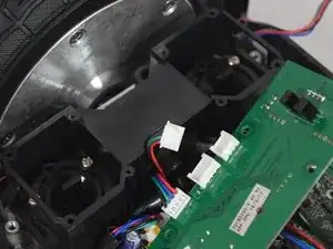
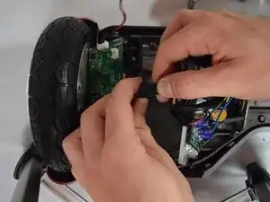
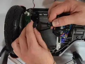
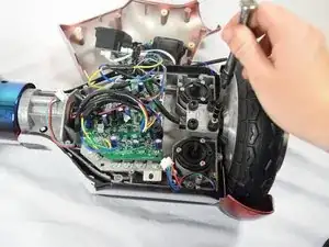
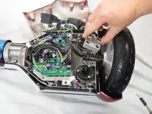
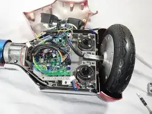
Is one side of the hoverboard not functioning, or unresponsive? This is a guide to show you how to replace the wheel, or motor (which is apart of the wheel) on the Hover-1 Horizon. This guide requires a Phillips #2 and a Phillips #1 screwdriver, and a 6mm hex key.

  1. wef5PQQeoVqct5fA
    wef5PQQeoVqct5fA
    VnWAZv3ULWi2HpYH
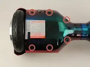
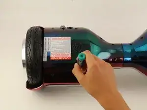
    • Remove the six 12mm Phillips #2 screws holding the base plate.

  2. bv2ddOjtHCbES1Y2
    bv2ddOjtHCbES1Y2
    2vC1sW2n5c16M5XW
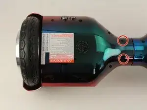
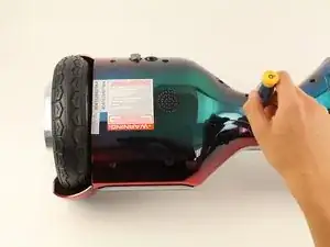
    • Remove the two 11mm Phillips #1 screws that hold the base plate to the body.

  3. yJ3y3DX1xQnkUeVG
    yJ3y3DX1xQnkUeVG
    UV5VTy2cTv6fjnfG
    QZeiIAAD2mOFWjFK
    • Remove the base plate by lifting it up.

    • The base plate is connected to the body with wires. The wires are long enough to set the base plate to the side.

  4. HEn26CdICIB1CYCU
    HEn26CdICIB1CYCU
    CpBcWAEA4k2EXNQp
    GnRXPZcYDwPGDKLV
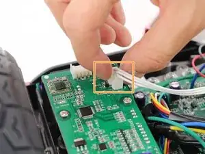
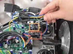
    • Remove the two connectors on either side of the board by lifting the tab and pulling out.

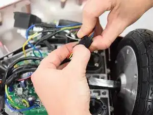
    • Remove the connector in the middle of the board by squeezing the tab and pulling up.

  5. INcNwdwBDhYGN61u
    INcNwdwBDhYGN61u
    6cVoNVUqVMrCvqPN
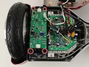
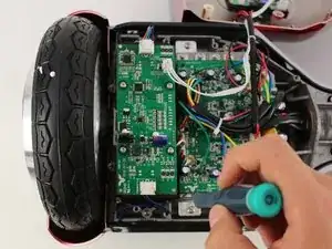
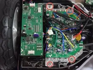
    • Remove the four 11mm Phillips #1 screws that hold the cover on.

  6. YXTAaCtLBmq4d3ki
    YXTAaCtLBmq4d3ki
    DYm6xwM25PsxFpcO
    CyWLfNRHhEROViwZ
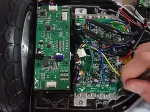
    • Remove the four 11mm Phillips #1 screws that attach the gyroscope board to the mount.

    • Lift the board to reveal the connections on the bottom.

  7. odZvcFuqkFMqvdFR
    odZvcFuqkFMqvdFR
    JZbLILGpgu4ITiqc
    • Remove the middle connector by squeezing the top of the tab and pulling up.

  8. PvAEN2AA3ABDSSTj
    PvAEN2AA3ABDSSTj
    NJyfeGFjqA4jwuR2
    2xgGAEhLP2he5CVW
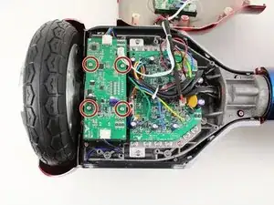
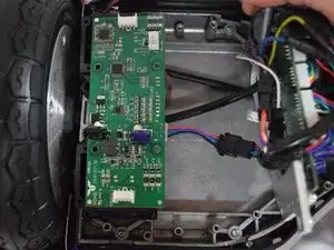
    • Remove the four 12mm Phillips #2 screws that hold the motherboard to the base.

    • Pull the motherboard away from the gyroscope by grabbing it with two hands and pulling it to the right .

  9. poDWtZYPrHM3KqHr
    poDWtZYPrHM3KqHr
    ODPO4VI6mgZCaUbN
    dns3UEpeoIyNib1Y
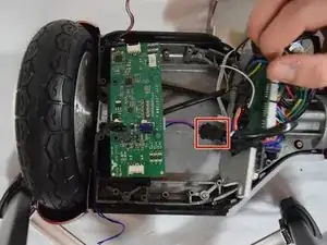
    • Unclip the black connector by squeezing both sides and pulling them apart.

  10. U2TMJBhrUPaMLAbt
    U2TMJBhrUPaMLAbt
    BpJbi35hXZVjy2xQ
    hkF3htNZIFAB5pfX
    • Remove the four 30mm Hex #6 screws.

    • Lift away the silver bracket and set it to the side.

  11. RCBwWLi6QVZrA1fF
    RCBwWLi6QVZrA1fF
    bQfQqrI5yUwAOWfd
    FNnt4BtBjlawOArB
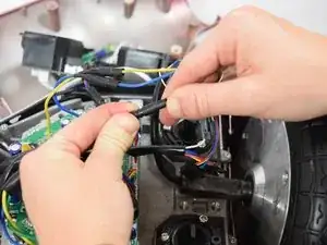
    • Disconnect the first clip by squeezing the latch that hold the clips together while pulling apart.

    • Disconnect the second clip by squeezing the tab while pulling the clip apart.

  12. fWBAVRvrgeF1vVoM
    fWBAVRvrgeF1vVoM
    TOAAWqcXIKhGVFSh
    42qoTJ5sjyLE44XY
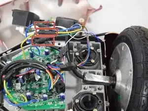
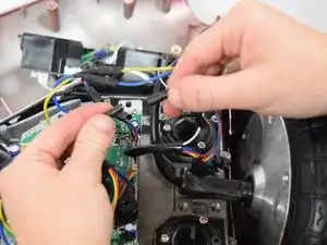
    • Detach the remaining three connections by pulling them apart.

  13. oSLtLBTCcnFQMHYq
    oSLtLBTCcnFQMHYq
    iuhkgeN1KDDWI36a
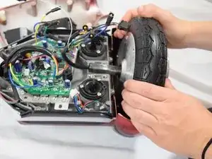
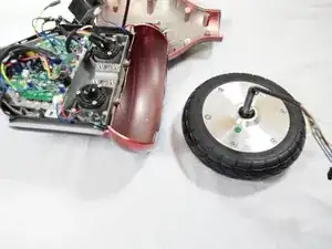
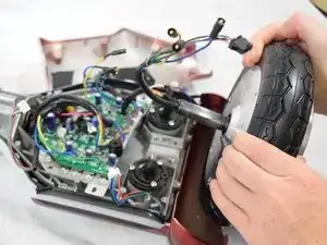
    • Remove the wheel by lifting it away from the base with both hands.

Abschluss

To reassemble your device, follow these instructions in reverse order.
Casey Winans

Mitglied seit: 08/10/18

324 Reputation

0 Kommentare